Front Suspension Bushings and Ball Joints
Joe Angell
For close to a year I had a weird vibration when braking and sometimes when hard cornering. The car would also pull to the left when hard barking. I tried a few things to fix it, such as replacing the steering rack and swapping the wheels, rotors and wheel bearings between the left and right sides, but none of that helped.
I finally posted to DMCTalk, and the consensus was that it was probably the lower control arm bushings. Dave checked and found that the rubber had delaminated from the metal of the bushings, causing them to shift more than they should. They were probably the original bushings from 40 years ago, and needed to be replaced. I later did the upper control arm bushings as well, so I’ll cover both here.
Suspension Components
The suspension consists of a few specific parts, and you’ll be taking most of them out:
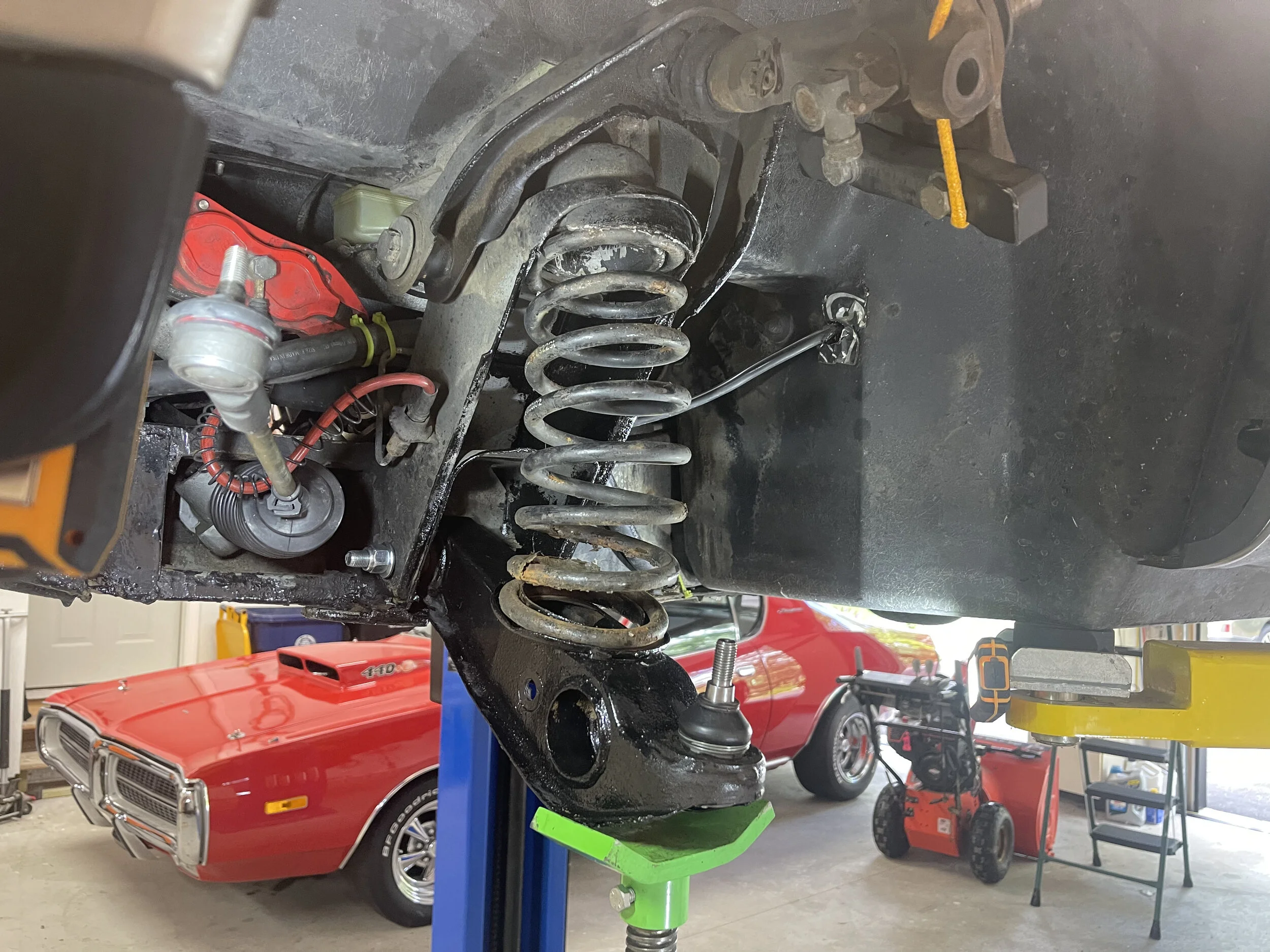
The lower control arm (LCA). This is attached to the frame with a pivot bolt, and has a cup to hold the spring, a hole for the shock, a place for a ball joint to attach to the steering knuckle, and a hole for the sway bar.
The steering knuckle, which is attached to the upper and lower control arms by ball joints, to the tie rod end by another ball joint, and carries the wheel, rotor and brake caliper.
The upper control arm (UCA), attached with a single long bolt through the shock tower.
The spring, which surrounds the shock and extends from the shock tower to the cup on the lower control arm.
The shock, which extends through the top of the shock tower and through the bottom of the lower control arm, where it is secured with a bolt.
The sway bar, which is mounted under the front frame extension via two brackets, and which runs through the lower control arm.
Pretty much every part ha bushings. these keep from having metal move against metal, and were originally rubber but some can be replaced with polyurethane ones that some feel give a more control and durability in exchange for a stiffer ride. Some are pressed, but others just slide into place.
The LCA has a bushing at the pivot bolt (pressed).
The UCA has two bushings for its pivot bolt (pressed; it’s a “U” shape, with one bushing per arm of the “U”).
There are two bushings at the top of the shock where it goes through the shock tower (slide on).
There is a rubber isolator at the top of the spring in the shock tower (placed).
There are two bushings on each side of the sway bar where it goes through the each control arm (slide on).
There are also a total of three ball joints: upper control arm, lower control arm, and tie rod end. Each of these are installed differently, with the UCA one being bolted on, the LCA one being pressed in, and the tie rod end one coming with the tie rod end, which just screws on.
New Parts
I decided to replace as much as I could without replacing the actual arms themselves, as long as I was in there. This included (note that the part numbers might not quite be right; be sure to check the parts manual before ordering):
New pivot bolts for the UCA (100479) and LCA (100477), and washers (100480, SP10505, SP10058, 101289) and nuts (SP10059, SP10027).
New upper ball joints. I went with DeLoreanGo’s UK-made ball joints (109271A) and all new mounting hardware.
New lower ball joints. I originally bout some with nylocks. I do not recommend this, as something ailed on me and the nylock disappeared one day while driving. I strongly recommend getting either DeLoreanGo’s UK-made ball joints (109266) with the optional castle nuts (SP10877), or DeLorean Texas’ NOS ball joints with castle nuts. Either way, get the castle nuts.
New front shocks, which included new bushings. I just got stock-style ones for now.
New shock bolt (101341) and washers
New sway bar bushings (108912 or 108912PU).
New lower control arm bushings (100154).
New upper control arm bushings (100156).
DeLoreanGo LCA Reinforcement plate (105177R)
The only thing I didn’t replace was the springs, which I should do at some point since mine were likely cut by the previous owner to lower the ride height. I actually do like the lower ride height, but uncut springs would probably be good to have.
I’d just replaced the steering rack and tie rod ends, so I didn’t do those again. I also didn’t replace anything on the wheel, since I’d already done the bearings and the brakes and the big nut doesn’t really go bad.
Replacing the Lower Control Arm Bushings
So pretty much all of that has to come out if you want to replace the bushings.
Removing the Tire, Wheel and Separating the Lower Control Arm from the Steering Knuckle
This is pretty straight forward, or it is to me, since I’ve done it a few times now.
Remove the lug nuts and tires (19mm socket) and the tire.
Remove the brake caliper.
Remove the angle drive dust cap (driver’s side only) and large central nut with a 1 1/4” socket (or metric equivalent).
Remove the “D” shaft washer under the nut.
Remove the wheel and brake rotor.
Remove (or at least don’t lose) the spacer behind the wheel.
Remove the three bolts holding on the dust shield for better access (optional, and I don’t have it on the Big Brakes system).
Disconnect the angle drive (optional? Driver’s side only)
Remove the nylock (17mm socket) on the tie rod end ball joint, then separate from the steering knuckle with a pickle fork.
Remove the cotter pin and castle nut (17mm wrench) from the lower control arm ball joint and separate from the steering knuckle with a pickle fork.
Hang the upper control arm and steering knuckle out of the way (or remove the UCA, if you prefer — it’s just one bolt).
The first step is to remove the tire with a 19mm socket. I have a very basic Ryobi cordless impact wrench that works great for this — powerful enough to remove the nuts, but not so powerful that it can over-tighten or otherwise damage the wheel studs.
Remove the plastic dust cap on the end of the wheel and take off the large nut with a 1 1/4” socket. This holds wheel onto the steering knuckle. There is a “D” shaft washer behind the nut; be sure to collect that and put it aside with the nut.
The brake caliper needs to be removed. For the UK Big Brakes system, this is just a couple of socket cap screws. I unclipped it and hung it from the brake line for the moment. Not great, but once the wheel was out of the way I was able to stash it on the front frame extension. Of course, I then forgot to move it back before I reconnected the steering knuckle.
You can now pull the wheel and rotor right off the shaft and set it aside. There is a spacer right behind it on the shaft. Don’t lose that, and don’t forget to put it back on.
Disconnect the angle drive behind the wheel. Mine has been disconnected for years, since it just breaks after a few hundred feet anyway, so I was able to skip this step. The angle drive itself can stay where it is.
Loosen the nylock on the tie rod end’s ball joint almost all the way with a 17mm socket, then use a pickle fork or tie rod end separator (which is just a pickle fork sized properly for tie rod ends) to separate the tie rod end from the steering knuckle. You just put the wedge-shaped fork between the two, and tap it with a hammer to push them apart. I left the nut on while I separated them so that they wouldn’t fly apart too far once they broke free. Unfortunately, the pickle fork I had was far too large, so I had to get a new one at the local auto-parts store. I also managed to damage the tie rod end ball joint boot trying to separate it (I later ordered a replacement from boot DeLoreanGo). Once the ball joint is free, you can push that end of the rack out of the way.
At the lower control arm’s ball joint, first remove the cotter pin, and then the and castle nut with a 17mm wrench, then use a pickle fork to separate the ball joint from the steering knuckle. You can now hang the upper control arm out of the way (I looped a bungie cord around the trunk piston for this). If you want, you can remove the upper control arm as well — it’s just one bolt.
Using a 1 1/4” socket to remove the wheel nut (passenger side).
The tire, wheel and rotor removed from the car. The brake caliper is haphazardly dangling by its brake line for now, but once the lower ball joint is disconnected from the steering knuckle I was able to move it around an place it behind the radiator.
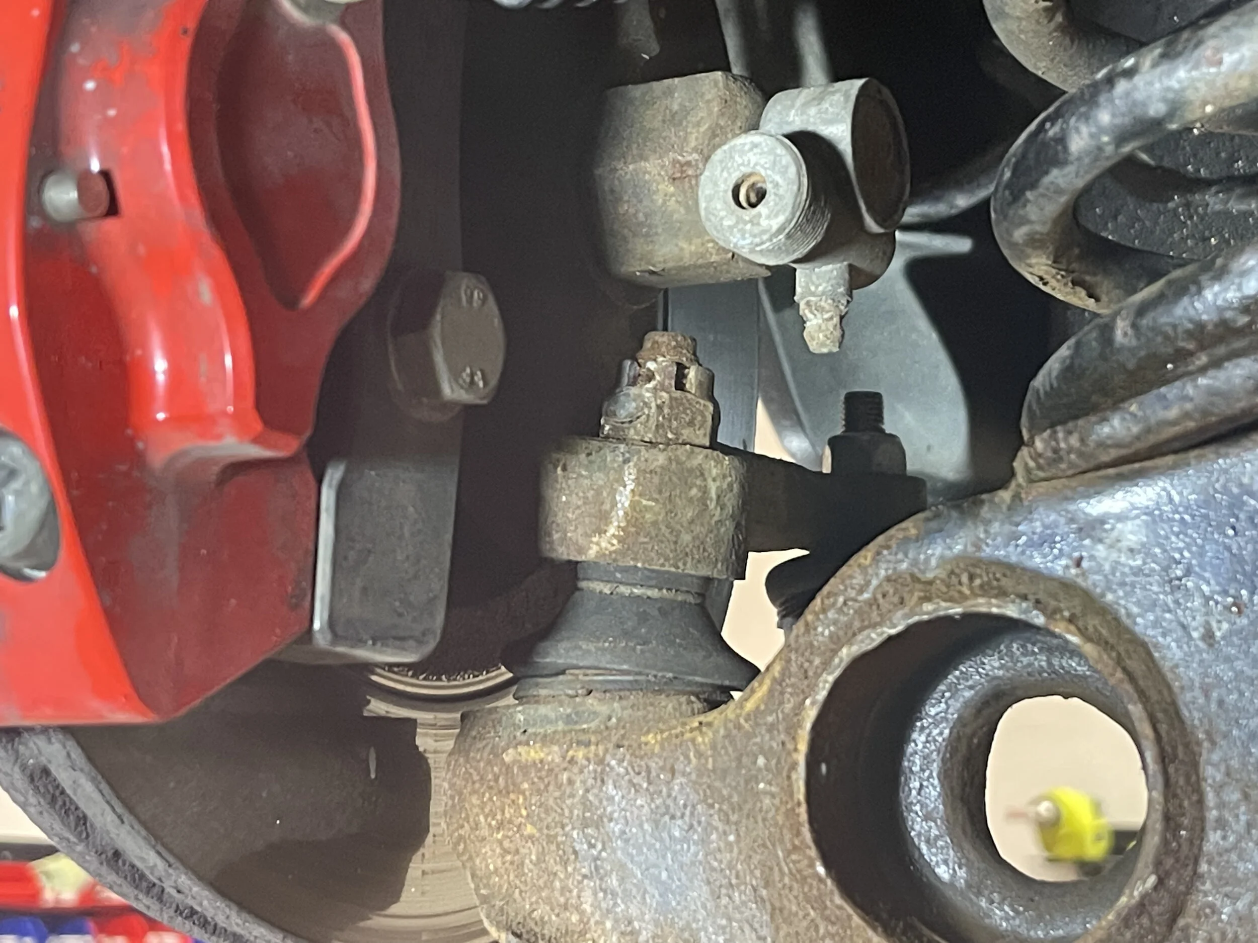
The castle nut that holds the lower ball joint to the steering knuckle.
An allen wrench is used to remove the two bolts on the Big Brake system (passenger side).
The wheel nut and the “D” shaft washer.
The wheel and rotor removed from the car.
Using a pickle fork to separate the tie rod end ball joint from the steering knuckle. Note the nut left loose on top so that it doesn’t completely separate.
The tie rod end removed from the knuckle.
The castle nut is visible at the bottom of the steering knuckle, with a shiny, fairly new cotter pin on it.
Once the cotter pin has been removed, the nut can be backed off with a 17mm wrench.
The steering knuckle removed from the LCA and suspended out of the way.
A bungee cord wrapped around the trunk piston is holding up the UCA and steering knuckle.
Removing the Sway Bar
The swap bar runs along the front of the car to stabilize the steering, and keeps the LCAs from swinging backwards and forwards Since it runs through the LCAs, it needs to be removed as well.
One side of my sway bar had a nylock, while the other side had two thin nuts. In both cases there is cotter pin to make sure the nuts don’t come off. I removed the pin with pliers and the nuts with a 19mm socket, and then went under the front frame extension and removed the four bolts that held the two sway bar brackets in place with a 17mm socket. You can then “squeeze” the sway bar by pushing an end of the bar towards the center of the car and and pulling it forward to free it from the LCA. One of the bushings will probably fall out the back side of the LCA, while the other will either stay in the LCA or stick to the swap bar. I had a bit of a mix, and the central metal shaft came out with the sway bar instead of staying with the bushings, but they were in good shape so I left them there.
The sway bar is the leftmost nut on the LCA. I have already removed the cotter pin in this picture.
The swap bar disconnected from the passenger side LCA, in this case before I separated the tie rod end ball joint from the steering knuckle.
The rubber sway bar bushings and the shaft can still be seen inside the LCA.
Removing the bolt from the sway bar bracket with a 17mm socket.
The sway bars completely removed from the car.
The sway bar on the floor, with one of the brackets still stuck to it, and the bushing shaft seized to the driver’s side end.
Removing the Shock
The LCA is now held in place by the spring on the bottom of the shock, and the pivot bolt on the frame side. The arm is under load from the spring. To remove the spring, you first need to remove the shock. The shock is limiting the travel of the spring, so you can’t just pull the bolt out.
The order is:
Support the control arm.
Remove the lock nut on the top of the shock.
Remove the other nut on the top of the shock.
Remove the washers and bushing from the top of the shock.
Remove the nylock and bolt from the bottom of the shock.
Compress the suspension with a jack and remove the shock from the bottom of the control arm.
Recover the spacers that may be on the bottom of the shock, and the remaining bushing and washers on the top of the shock.
First, we’ll cover the wrong way to do this.
I put a jack under the end of the LCA near the ball joint and raised it to remove the tension on the shock. I then removed the nylock on the shock bolt, and use a wrench to remove the bolt itself. The shock is still under tension because it wants to expand, so it won’t just pull out. If you have a second jack you can try to put it under the base of the shock to remove some tension, but I just twisted it out a socket on a power drill.
If all goes well, the bolt will come out and the LCA will be supported by the jack. If you do it wrong like I did, the LCA will suddenly drop, knocking over your jack and making a loud bang. I had the jack in the wrong place, and didn’t have it actually supporting the LCA, just resting under it. I was also being paranoid, where I held the drill at arm’s length and stood well back, so I wasn’t injured, but I could have been. The LCA dropped basically instantly to its lowest possible position as the shock came free and the spring suddenly had nothing keeping it in place.
The right way is much simpler and safer.
Support the lower control arm with a jack near the ball joint. Then remove the lock nut on the top of the shock tower, and then the other nut. As you remove the lower nut, the shock may slowly retract towards the bottom of the LCA. Once the nuts are off, you can remove the bushing and washers on top. Now the shock is only connected through the bolt on the bottom that goes through the LCA. You can easily remove the nylock and that bolt.
To actually remove the shock, you’ll likely need to compress the spring by jacking up the lower control arm. This is because the spring bends a bit and presses against the shock. The bottom of the shock can be pretty tight against the LCA, so you may have to tap it to get it to fall free. There is also another bushing and pair of washers on the sock’s shaft.
At the base of the stock shocks there are two spacers that bolt runs through. Other shocks may not have these spaces, including the new basic shocks from DeLorean Texas. I kept them just in case I needed them in future (which I did, we I later helped Adam Harriot replace his shocks)
Adding a bit of penetrant to the bolts before removing them.
A 14mm wrench is needed fort he two nuts on the top of the shock tower.
Removing the top nuts. Notice the suspension is supported by a jack, in order to keep it from dropping while loosening the nuts.
Removing the Spring
The spring is the most dangerous part of this entire process due to the amount of stored energy it contains. You can’t just pull it out by hand, and if you try to pry it out you’ll likely seriously injure yourself or damage the car or both. You need to use a spring compressor.
You can get a loaner compressor from most any auto-parts store. The ones that have two bars that separately clamp on opposite sides of the spring work well. I decided to buy my own clamshell-style one from JEGS.
Clamshell compressors look sort of like giant staple remover. Since the clamshell design is a single unit, it is less likely that the spring will come loose and become a danger. The two upper claws hook onto the top of one coil, while the lower ones hook onto the bottom of another coil. You want these to be as far apart as possible so that the compressor grabs as many coils as possible and thus can compress it as much as possible.
Before you begin, you should oil the central bolt on the compressor to keep it from binding. You can then try to hook it onto the coils. I say “try” because the hooks won’t simply fit between the coils. You’ll probably be able to tilt the compressor to get a couple of hooks on, but it’s hard to get those last two on. I finally resorted to grabbing a pry bar and bending the coils apart enough to fit the hook through. This is relatively safe because the spring is still contained by the car’s suspension system, but you do still want to be careful, and make sure to not get any fingers anywhere that they can be crushed if the pry bar slips while inserting the compressor. Make sure you engage the safety pins on the compressor once coils are hooked.
Once you have the compressor in place, and you’re sure that the top hooks are on the same coil, and that the bottom hooks are on the same coil, you can start turning the bolt on the top to compress the spring. You should do this by hand, and not use power tools like an impact wrench. You can close the compressor as far as possible as long as the coils don’t touch each other, although my compressor bottomed out before that. My tool also included a safety loop that hooked over the side of the compressor to keep it from popping out too far if something went wrong.
To make it easier to compress the spring, you can jack up the suspension. The idea is that the jack takes the load of the spring, and now you can turn the compressor bolt more easily. You can repeat this until the spring is compressed, then carefully lower the jack. You want to make sure that final compression is done by the compressor, not the jack.
Even when fully compressed, I still couldn’t quite get the spring out, but just barely. It was clearly loose and there wasn’t any tension, so I used a pry bar to carefully shift it just enough to get it free. If the spring is not clearly lose and shifting around, you cannot do this, as the spring will have too much energy and will likely damage something or injure you or both.
You can now remove the compressor and spring together and carefully set it aside. Put it someplace where you won’t trip over it or otherwise jostle it in a way that will risk the spring coming free.
The spring compressed as far as the compressor would go. The safety is installed in this picture.
The spring removed and compressed by the clamshell-style spring compressor, with the safety brace looped around the two posts.
The shock and spring removed from the car. Only one bolt holds the LCA in place now.
When I did the passenger side, I removed the upper control arm as well.
Removing the Lower Control Arm
The only thing holding the LCA into the car now is the pivot bolt. Remove the nylock, then pull the bolt out while supporting the LCA, and your LCA is finally free of the car.
The LCA out of the car and on the bench.
The empty space where the front suspension used to be. The brake caliper is stored behind the radiator for the time being.
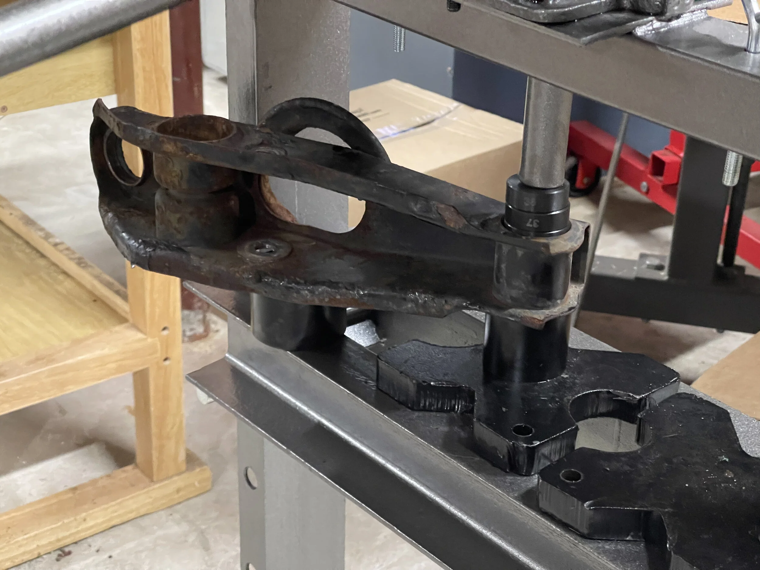
Removing the Bushing
The bushing needs to be pressed out. I have a basic 12 ton Harbor Freight press that I could use for this. I purchased a bearing push set from Amazon that contained a series of metal discs of different sizes. It also had the tools to push and pull bushings directly, but I was interested in the discs themselves. This is because you need a shape pretty close to the actual size of the bushing as possible to push it out. Too small and you won’t push it evenly or may slip or misalign it, and too large won’t push the bushing. Ideally, you’d push on the metal rim on the edge, but the design fo the bushings is slightly conical and hard to do, so you’ll likely have to push from the center. Mine came out pretty easily by using a stack of discs.
Pressing out the old bushing.
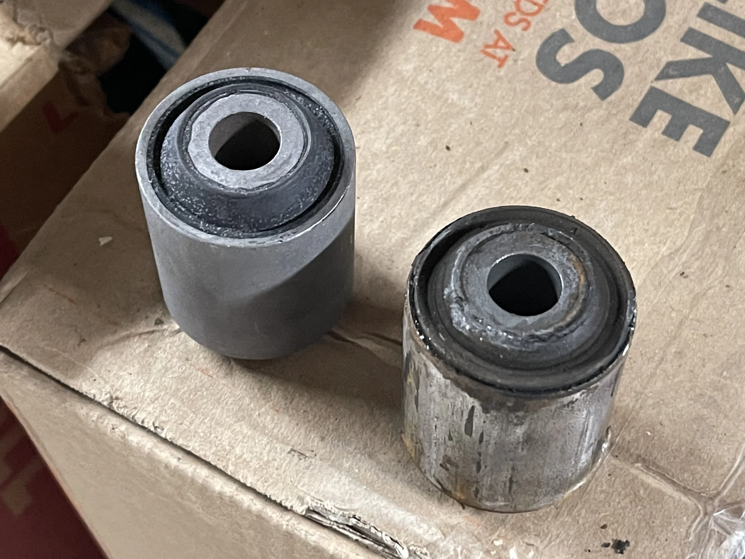
The new bushing (left) and the old one (right). It doesn’t look too bad here, but the rubber isn’t properly laminated to the metal frame anymore.
A ball joint press (top) and a set of press discs (bottom).
Removing the Ball Joint
To remove the ball joint, you’ll want a ball joint press kit. In fact, you probably want do this in the car, but you can use a press if you like.
Remove the snap ring at the base of the ball joint.
Remove the boot on the ball joint.
From the ball joint bit, place a disc over the top of the ball joint shaft so that it rests on the ball joint, so it can press the shaft and joint downward.
Place a hollow cylinder around the base of the ball joint inside the bottom of the LCA. The ball joint will be pushed through this cylinder.
Use the frame (the C-clamp) to press the ball joint out of the control arm.
There is a snap ring at the bottom of the ball joint that keeps it from dropping back through the LCA. It may be buried under 40 years of road junk, so you might overlook it. I didn't even notice it and somehow managed to push the first ball joint out. I never found it, so I’m wondering if it was even there.
You can get a loaner kit from an auto-parts store. It consists of a C-shaped frame, a long screw, some heavy discs with holes through the middle, and a series of hollow cylinders. I used a loaner for the first one, then bought my own because I just like having my own tools.
To remove the ball joint, you place one of the discs from the kit over the shaft. You then place the smallest cylinder that fits under the LCA and clears the body of the ball joint, and place the other disc on under of that. You then use the C frame and screw to push the ball joint down through the LCA and into the empty cylinder.
You should remove the boot from the ball joint first. This makes it much easier to push it through the LCA, as otherwise the retaining ring and the boot itself will be in the way and have to be pushed through as well and likely damaged. I did it the hard way for my first ball joint, but I removed the boot for the second.
I did this on the car by temporarily mounting the LCA with its pivot bolt. I was then able to crank down on the press screw with a wrench until the ball joint popped out the bottom.
The stack of tools to remove the ball joint: a press disc, a press cylinder, the ball joint, a second disc, and the frame and screw.
The LCA with the bushing and ball joint removed, ready to be reconditioned.
Welding a Reinforcement Plate
The lower control arms have some weakness in their design. There are a few upgrades that can be done, such as installing outriders, ore getting new heavy duty aluminum or stainless steel LCAs. I went one of the simpler (and cheaper) updates that many others have done, which is to weld plates to the bottom of the LCAs. The open “U” shape of the LCAs makes them more flexible and susceptible to collapsing if something goes wrong. Rather than fabricating my own plate, I purchased pre-made plates from DeLoreanGo. You’ll want to weld these in before installing the new bushings to avoid damaging the bushings with the heat.
The plates are shipped flat, but the LCA has a curve to it. This isn’t a big deal; you just clamp the plate down, then tack weld it at a couple of the points that are touching the LCA, then bend it, clamp it, tack weld it, and so on until the plate is properly formed to the LCA. Then just go back and finish welding between the tacks.
Before I started, I used an angle grinder to remove any rust, paint and epoxy where I would be welding. My welds were good enough for the purpose of this job. I used an angle grinder to clean them up, and then painted the entire arm with POR-15 to protect it from rust. I also painted some parts of the frame behind the LCA that were rusty. I let them dry overnight and reinstalled everything the next day.
The start of welding the reinforcement plate to the bottom of the LCA. I tacked it and bent it until the entire thing was formed, then finished welding it.
The final welded plate. Not the prettiest thing, but it works.
The painted LCA drying overnight.
The final painted LCA.
Cleaning Up the Frame
With the LCAs out, I could inspect the frame There was some minor rust on the driver’s side that was easily patched up with POR-15.
The passenger side had more rust, and one of the layers of sheet metal seems to have flaked off, but it wasn’t compromised. Inside the frame behind the LCA needed rehabilitation, too.
I peeled off the brittle epoxy and scrapped off all the loose metal I could find. I used a rag on a stick to drag out as many pieces as I could, and vacuumed out the rest as much as possible. I POR-15’ed everything accessible, and sprayed epoxy gray Rustolium into the cavity for the rest.
POR-15 applied to the rusted areas of the frame behind the LCA on the driver’s side.
Rust wire the control arms mount on the passenger side.
Dragging out the debris with a rag on the end of a pry bar.
Inside the box on the passenger side, after cleaning it out. This was later spray painted to protect it.
All the debris from knocking off old epoxy and rust (sway bar for scale).
Removing the Upper Control Arm and Bushings
Not too long after, I did the upper control arm as well. The UCA isn’t connected to the spring or shock, so it is much easier to deal with. I also replaced the upper ball joint while I was there.
A single long bolt secures the UCA to the frame. Just remove the nylock and tap out the bolt with a brass hammer.
The steering knuckle is connected to the UCA with a ball joint. In theory, you just remove the nut and it comes right out, but my passenger side one was stuck and had to be cut off. John Dowd did the honors there with an air grinder. Back home I had to do the other one myself. I couldn’t turn the nut or the ball, but I could disconnect the ball joint from the UCA, which gave me access to put an angle grinder on it. After cutting off most of it, I had to grind away the rest before I could tap it out of the knuckle. It took about 20 minutes to figure it out, but it worked.
To remove the ball joint from the UCA, you just remove the four sets of nuts from the screws that hold it on. A stock setup uses four nuts plusd four extra lock nuts on four bolts, while the UK-made replacement set I got from DeLoreanGo used slightly smaller M6 bolts and nylocks.
Replacing the Upper Control Arm Bushings
The UCA bushings are installed with a press, just like the LCAs. However, the open side of the UCAs make this a bit trickier. If you just start pressing, the UCA will deform. You need something to keep the open side open.
A post on DMCTalk noted that it’s about a 1” gap, and that 1” square stock will work just fine. I bought a length and cut it into two pieces, and wedged those on other side of the LCA. I then used my disc kit to find a disc that would allow me to push them out, and installed the new bushings in the same way.
I did the second arm a week later, and had the foresight to put the bushings in the freezer. This shrank them and made it easier to press them in. I should have done this for all the bushings.
The upper ball joint disconnected from the UCA, with the bolt partially cut with a Dremel before I realized I could unmount it and get an angle grinder in there.
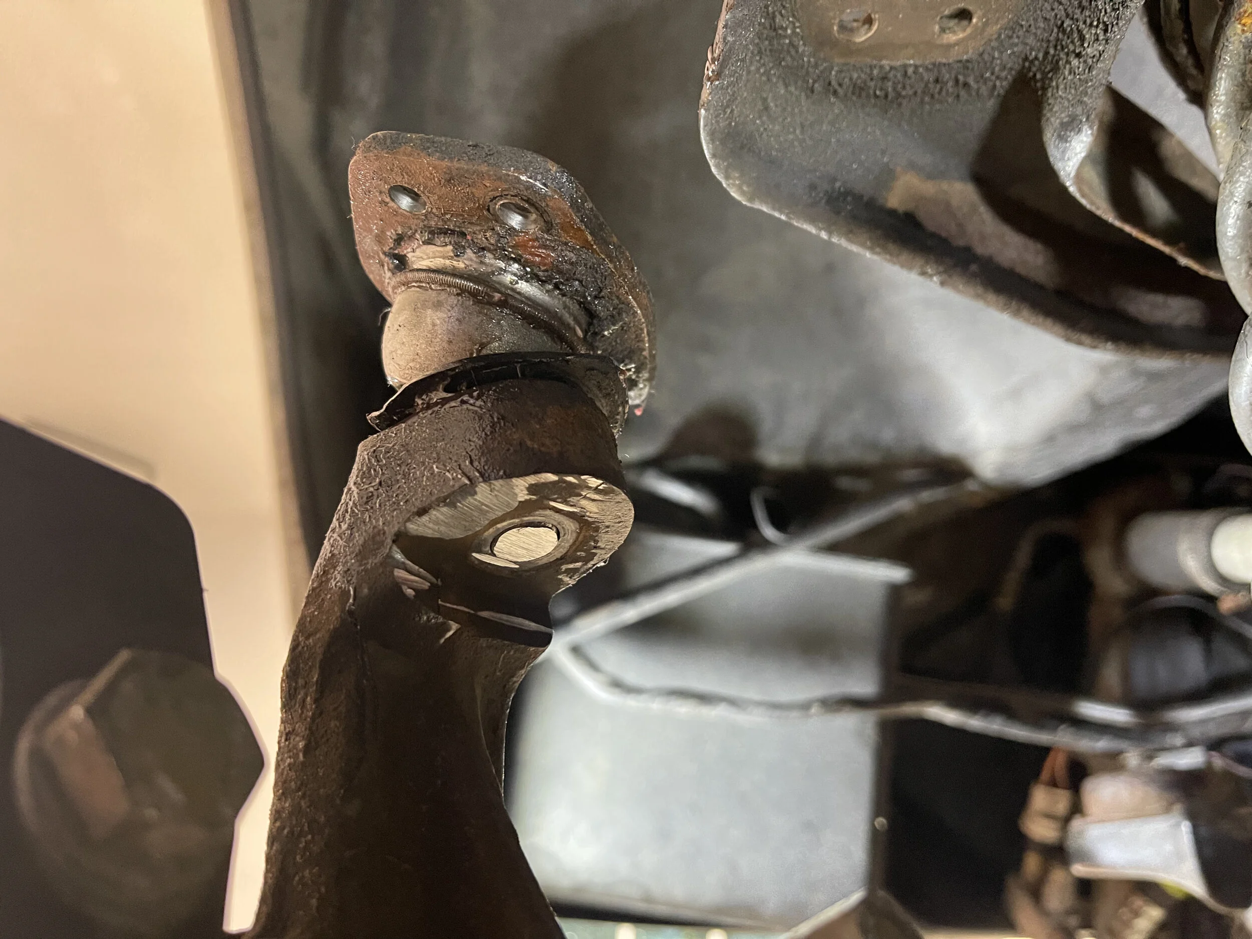
The nut cut off the end of the upper ball joint, ready to be tapped out.
Incorrectly Installing the Upper Control Arm Bushings
Now, let’s say that you forget to put the square stock reinforcements in while pressing. You’ll wind up bending your UCA. And that’s exactly what I did. A smart person would have ordered a new one from DeLorean Texas complete with new pre-installed bushing. An impatient person would try to fix it.
So I used the press to flatten out the deformed parts, and then pushed the new bushings in. This actually worked reasonably well. Not that I recommend anyone else do this, but the bushings seemed to fit properly in the arm, and the arm seems structurally sound enough.
When I reinstalled it in the car, I found that the arm was now wider than it was before. This made it far, far easier to put on the washers that sit between the inside of the UCA’s “u” and the frame. On the other side it was so tight that there was no way I would be able to fit the washers in there. When I tightened the nut on the end, the UCA compressed cleanly with no gap, and the load bearing parts were still in good condition.
I really, really should order a new UCA, just to be safe. They’re not even that expensive.
Reinstallation
Installing the Upper Control Arm Ball Joint
This was very easy. I covered the old bolts and nuts with penetrant, but this didn’t seem to be necessary — they came off very easily. I lined up the ball joint (it only fits properly one way), then put the new bolts and nylocks on. Piece of cake.
Using two pieces of 1” squar estock to support the open side of the UCA while pushing in the bushings.
Another view of the bushing being pushed in.
Incorrectly Installing the Upper Control Arm Bushings
Now, let’s say that you forget to put the square stock reinforcements in while pressing. You’ll wind up bending your UCA. And that’s exactly what I did. A smart person would have ordered a new one from DeLorean Texas complete with new pre-installed bushing. An impatient person would try to fix it.
So I used the press to flatten out the deformed parts, and then pushed the new bushings in. This actually worked reasonably well. Not that I recommend anyone else do this, but the bushings seemed to fit properly in the arm, and the arm seems structurally sound enough.
When I reinstalled it in the car, I found that the arm was now wider than it was before. This made it far, far easier to put on the washers that sit between the inside of the UCA’s “u” and the frame. On the other side it was so tight that there was no way I would be able to fit the washers in there. When I tightened the nut on the end, the UCA compressed cleanly with no gap, and the load bearing parts were still in good condition.
I really, really should order a new UCA, just to be safe. They’re not even that expensive.
What happens when you forget the spacers when pressing the new bushing in. I was able to mostly fix i
The new bushings installed after flatting out the bend arm end. I’m sure it’s fine…
Reinstallation
Installing the Upper Control Arm Ball Joint
This was very easy. I covered the old bolts and nuts with penetrant, but this didn’t seem to be necessary — they came off very easily. I lined up the ball joint (it only fits properly one way), then put the new bolts and nylocks on. Piece of cake.
The newly repaired and UUCA instaleld in the car with its new ball joint.
Installing the New LCA Bushing and Ball Joint
The new LCA bushing goes in the same way it came out, with a press. The hard part here is that the bushing is slightly recessed, and you can’t see how recessed you’ve made it until you withdraw the press. It took me about 10 cycles to get it to the right depth, as I was worried that I would push it too far and instead kept not pushing it far enough.
This is the sequence for how you should do it:
Remove the rings holding the boot onto the ball joint.
Remove the boot itself.
Using the ball joint bit, place a cylinder over the top of the ball joint shaft so that it rests on the control arm, and put the matching disc from the. kit on top of it.
Place a second cylinder along the outer edge of the bottom of the ball joint, and place the matching disc under it.
Use the frame (the C-clamp) to compress the ball joint into the control arm.
Since I hadn’t done this before and didn’t bother to look at any videos or anything, I did it a bit differently, and made a few mistakes, but none critical
You should start by removing the boot from the ball joint. I didn’t on the first ball joint, which made it much harder to press in and ruined the boot. There are two coiled rings not much different from a keychain on the top and bottom of the boot. I removed these with a pair of pliers, prying one end out and up, then sliding my pliers around to pull them up off the top of the boot.
You can position the ball joint and get it started by tapping it in with a hammer from below. Be sure to either use a socket or remove the grease fitting so that you don’t damage it. Make sure that the hole in the ball joint fro the castle nut cotter pin is perpendicular to the arm, as this will make it much easier to install it the pin in the car later.
The ball joint can be installed with the ball joint press, but the cylinders mine came with were too shallow or the discs too wide to clear the control arm body as it is pressed the ball joint in from the bottom, so I went back to the press. I used one of my bushing install kit discs for this, as it had a hole in the middle that fit around the grease fitting that would have been crushed if I’d used the press directly (although you probably want to remove the fitting in case something slips; it’s just screwed in there and comes off quite easily with a small wrench or even some pliers). I probably could have used these on the car as well, but if something slipped under pressure it might have sent a disc flying, and I didn’t want to deal with that. A sufficiently large socket would have worked, too.
I used one of the hollow cylinders from the ball joint press kit on the other side to keep the shaft clear of the bottom of the press. Unfortunately, I failed to align the arm properly and it shifted, causing the ball joint to shift and install at an angle. I wound up having to press it back out again, at which point I found the the ring that secures the boot to the body had gotten ruined as well, which also ruined the boot itself. This is why you should take the boot off first.
Luckily I had a second ball joint (for the passenger side LCA, which I’d do on another day). I removed the bottom ring on the boot (I should have removed the whole boot), positioned the ball joint in the arm, pushed the boot through the hole as much as I could with a flathead screwdriver, and then pressed it into the arm. It did go in on a little bit of an angle, but it flatten out once it was all the way down. I probably should have removed the boot entirely to make this easier, but it worked. I then snapped back on the boot ring. I later ordered replacement boots from DeLoreanGo.
The new ball joints come with new snap rings. I tried and failed to install this on the bench, and even broke one of my cheap snap ring pliers. Dave got the driver side one on with his Snap-On snap ring pliers while the LCA was in the car, which was much easier. He also put a coat of anti-seize under the ring to keep it from binding to the LCA over time. I have since ordered a set of OTC snap ring pliers from Amazon, for when I did the passenger side, which made the job far easier. John Dowd has an even nicer set of ratcheting snap ring pliers that hold the clip open while you’re trying to get it in place.
The final painted LCA with the new bushing already in.
Pressing in the new bushing. One fo the hollow cylinders from the ball joint press kit and a disc from the disc kit made it fairly easily. Getting it straight was a little tricky, though.
Another view showing the LCA almost completely pushed in.
The ball joint installed in the controller arm.
The newly installed ball joint with the split ring in place. Notice the orientation of the hole in the shaft. This makes it much easier to install the pin later.
Installing the Lower Control Arm
Before installing the LCA’s pivot bolt, I coated it with anti-seize. I mostly did this because the original one was coated in anti-seize, but it seems to be good practice to do so. I used a new bolt, washers and nylock. However, I did not tighten it yet. Well, I did, but Dave pointed out that you need to tension the nut under load, with the spring in place and compressed, so we wound up loosening the nut, jacking up the suspension until the car just started to lift off the jack stands (or lift pads, in my case), and torqued the nut to 60 ft lbs with a 19mm socket as per the workshop manual.
Installing the Spring and Shock
Installing the spring is as dangerous as removing it. I was able to get it positioned correctly with just a little prying to get it to clear the LCA. I placed a jack under the LCA’s ball joint, then loosened the bolt on the compressor until I could remove it. I again had to carefully pry some coils to get the hooks free.
At this point, the spring is bowing outward a bit, but it is contained and won’t leave the LCA. But the bowing interferes with installing the shock. I had to jack up the LCA until the spring was more straight so that I could fit the shock into it.
I installed new shocks from DeLorean Texas. For now I went with just stock-style shocks, which are inexpensive and install the same way as stock. In the future I’d like to do coil-overs, but that was out of my budget at this time.
The stock shocks use spacers one other side of the base of the shock for the bolt that runs through the LCA, but the new ones cane with a sleeve already installed. For some reason, this sleeve was slightly too long, and simply wouldn’t fit. I wound up grinding it down on both sides until it just fit.
Before putting the shock in the car, you need to add one of the washers on the end, then the bushing, then the other washer. There are two “styles” of washer, one with a ridge and one without. The one with the ridge goes on top, and fits in the hole in the shock tower. You can then insert the shock though the hole in the bottom of the LCA, through the spring, and through the hole at the top of the shock tower. Another washer-bushing-washer set go on top, and then the two nuts to lock it into place.
I found I had to compress the spring with a jack under the LCA to straighten it enough to let the shock line up the the hole in the top of the shock tower. This was easy enough to do, though.
For the bolt on the bottom, you need to compress the shock, which you should be able to do by hand by pushing up from the bottom while aligning the bolt through the hole in the LCA. The bolt should be coated with anti-seize first, and the appropriate washers installed. Once I got the bolt through the first side, I had to use a punch to align the shock so I could push it through the other side of the LCA. You’ll need to tension the suspension before torquing down the bolt to 60 ft lbs, just like with the LCA pivot bolt.
The spring placed and ready to be uncompressed. I almost forgot to take off the safety loop.
The spring installed in the refurbished LCA.
Both nuts installed on the top of the shock, on top of the washer, bushing and other washer.
Anti-seize applied liberally to the shock bolt.
Using a punch to align the shock shaft with the hole in the LCA so the bolt will make it through.
Tightening the shock bolt with the suspension tensioned.
Reinstalling the Upper Control Arm
The UCA and LCA can be installed in either order, or independently of each other. The UCA is by far the easier of the two to put in.
The main trick is that there are supposed to be washers between the UCA and the frame that it mounts to. After 40 years of being mounted to the car, it is difficult if not impossible to fit the washers in there. In fact, I didn’t even install them on one side, although I may go back and do it later. These washers provide a a surface for the bushing to rotate against. I only installed them on the other side because of how I had bent the arm a bit trying to get the bushings out, which inadvertently widened it and made it easier to fit the washers.
Once the pivot bolt is in, the nut should be torqued to 60 ft lbs while under load, just like the LCA,
Reinstalling the Steering Knuckle
The upper control arm ball joint is secured to the knuckle with a nylock in the newer kits. Just slide the shaft into the knuckle, then spin on the nylock and torque it to 35 ft lbs with a 17mm socket. I had some trouble getting it high enough on the driver side, and the ball joint started spinning, but we soon discovered that it just wasn’t far enough on the shaft. Once it was slide up properly, it spun on and torqued correctly. The passenger side was more annoying, and spun more easily. I tapped the ball joint down with a hammer to secure it against the shaft, and then was able to make a little more progress turning the nut again before it started spinning the ball. I repeated tapping and tightening until it was secure, then torqued it down as above.
The lower ball joint is a little bit different. You’ll likely need to jack up the suspension to get the ball joint shaft aligned with the knuckle. I had to do this on the passenger side, but not the driver side. You may have to tap shaft (but the nut on loosely, then tap it, to avoid damaging the threads) and shift things a bit to get it to actaully line up and fit properly.
I couldn’t get a socket on this one, because the knuckle was now in the way. I just tightened it as far as I could, then backed it off enough for the hole in shaft to line up with one of the spaces in the castle. I actually tried to go one more space, but I couldn’t get the nut any tighter — I think I was at the end of the threads. The nut isn’t going anywhere — the cotter pin is very thick and was very hard to bend (John tapped it with a screwdriver to spit it, and I was able to do some bending with pliers), and the nut is not going to be able to back off with that pin in the way.
I strongly recommend getting either the NOS lower ball joints from DeLorean Texas or the UK lower ball joints and optional castle nuts from DeLoreanGo. I originally got the cheaper lower ball joints with nylocks. Either I didn’t install them correctly or they failed, because I the ball joint separated from the steering knuckle while driving. That will be covered in another post.
Reinstalling the Rest
Everything else goes back on the way it came off. The tie rod end fits in the knuckle and the nylock is torqued down. The dust cover for the brakes goes back on, if you took it off. The brake caliper is moved back to the rear of the suspension, and the wheel is remounted, and the caliper reinstalled. The big nut (don’t forgot the washer) has a torque number, but since it’s quite high and out of the reach of most home torque wrenches, the rule seems to be “as tight as you can”. The angle drive cable is reconnected, the plastic dust cap reinstalled, and then tire is remounted and the lug nuts put back on. And that’s it — you’re ready to drive.
The completely reassembled suspension on the passenger side. All that’s left is the wheel, rotor, brake caliper and tire..
A few test drives later and the vibration issues seem to be pretty much gone. While it is an involved update, a lot of parts in this car are decades old, and the rubber is long past its life, so replacing them was probably fixing issues I didn’t even know I had.