Yet More Issues: Alternator, Water Pump, Fuel Pump, Sway Bar and Coolant Temperature
Joe Angell
And suddenly a bunch of problems happened at once.
Erratic Oil Gauge
We’ll start with the easy one: the oil gauge. Most of the time it was fine, but sometimes it would bounce around almost randomly. A quick investigation found that the gauge wire was resting on the exhaust manifold, which quickly burned through the insulation and shorted the gauge to ground. I replaced the wire and zip-tied it away from the manifold. Once problem down.
Keep your wires away from the hot exhaust components.
Squeaky Belt: Water Pump
My belt was squeaking, and it got more and more annoying. I thought the noise was coming from the center of the engine, so I decided to replace the water pump. Even thought it only had a couple thousand miles on it at best, the pulley had been rusty almost since I got it out of the box, so replacing it wasn’t a bad idea. I bought a new Remy pump from RockAuto. I cover replacing the pump in an earlier post, but I’ll recap it here along with some other things I learned.
Replacing the water pump isn’t that bad, but you have to remove a lot of stuff. First, drain the coolant from the engine. There are plugs on both sides of the engine block. I had an easier time accessing the passenger side one, and decided not to do the driver’s side one. This was a mistake — do both of them, especially on the 3.0L engine. Loosening the coolant bottle cap will make allow more coolant to drain by removing the vacuum that the evacuating fluid will pull on the system.
Next take off the belt. To do this you’ll have to loosen the nut at the top of the alternator with a 17mm socket and wrench, the nut on the adjuster arm with the same 17mm socket and wrench, and the nut on the other end of the arm with an 11mm socket and wrench. You can then tilt the alternator towards the engine and remove the belt.
With the coolant drained, I removed the 3.0L intake manifold. This is just four bolts and an 11mm socket, but I had to pull the spark plugs for access, and remove the fuel pressure regulator (two bolts with a 10mm wrench) to get the socket in there. I didn’t pull the manifold off the car — I just tipped it back and propped it up, being careful not to damage any hoses, fuel lines or wires in the process. The alternator light and oil pressure gauge wires didn’t reach that far, so I cut them and installed blade connectors to make it easier to do this kind of maintenance.
With the manifold out of the way, the water pump connections can be clearly seen. You should really put rags inside the cylinder holes to keep anything from falling in there, just in case, but I was lazy and didn’t. The back of the pump has to be swapped to the new pump, and I found it easiest to remove the pump, “Y” pipe and heater pipes together.
The “Y” pipe is held down with four bolts that can be removed with a 10mm socket.. One of these also holds the heater pipes in place, so you’ll need to remove it one way or another. The heater hoses connect to the pipes with hose clamps and are easily removed.
Next is the clamps on the hoses to the cylinder heads, which I loosened at the heads and at the pump. You could remove the flanges themselves, but then you have to replace the gaskets under them, so it’s probably easier to remove the hoses. Next is the hose on the right side of the pump. I didn’t remove the left (upper) hose, instead removing the thermostat housing itself. This housing has to be transferred to the new pump anyway, and it saved me from having to remove that hose clamp and the screw for the self-bleeder..
Finally there are three bolts holding the pump itself to the engine. These use an 11mm wrench. You can use a socket for two of them, but the third requires an open ended wrench. The bolt will not clear the pulley, and the new pump comes with a new bolt already installed so that you don’t have to worry about this. You will need to remove one of the idler pulleys with a 15mm socket to get to one of the bolts.
Now you can pull the water pump off of the engine. This is where you really want to have drained the block. Since I didn’t drain the passenger side, when I pulled the “Y” pipe upwards with the water pump, coolant rose up and filled the “V”. Once I got the pump out I had to use a siphon and a bunch of shop rags to clean up all the coolant.
Everything from the old pump is transferred to the new one. The back of the water pump is attached with four cap screws, and should come off pretty easily. The heater pipe that goes into the elbow on the side of the water pump should just pull out, although I had to tap the sleeve with a screwdriver and a mallet to get it to come loose. I did not try to remove the heater pipe from the back. There was no need to, and it also has some kind of crimped metal band holding it in place, which I didn’t want to mess with.
I did reuse the gasket from the old water pump. It was a nicer rubber gasket, while the new one came with a simple paper one that wasn’t even flat and split when I tried to flatten it. Some people don’t even use gaskets, and just use RTV. I used both the rubber gasket and RTV.
The other heater pipe should just slide back into the elbow on the side and lock into place. Mine felt looser than the old one, but didn’t leak once it was installed, so I guess that’s just how it is.
The short cylinder head hoses also need to be transferred to the new pump. These are just hose clamps, so it’s pretty easy. Don’t tighten the hose clamps yet, though; you’ll likely need to adjust the alignment relative to the cylinder heads.
Now you just have to put the pump and pipes back in the car. The “Y” pipe goes in after the other pipes. Be sure to replace the O-rings on the “Y” pipe. I didn’t, and then I got to take everything apart again when coolant poured out from the junction and filled the ‘Y”. You should also replace the O-rings on the intake manifold as well.
It can be a bit tricky to get the pump in place with the cylinder head hoses. I used picks to pull them around the flanges on the heads, finished seating the pump, bolted the pump to the engine, and then tightened the hose clamps. The side hoses were much easier to get on. The hose clamps for the heater core should be easy enough to install as well — just make sure not to mix up which line is which.
Finally, the thermostat and is bolted back onto the pump. make sure the hole on the thermostat is pointed towards the front of the car (the highest point in the housing). You can optionally use RTV on the seal to ensure that it doesn’t leak. I actually forgot to tighten one of the bolts on the housing, and it took me a surprisingly long time to notice that it was sticking well up from the surface and that that was why the housing was leaking.
Next replace the O-rings on the intake manifold, bolt it back down, secure the fuel pressure regulator, re-install the spark plug wires, reconnect any other wires you disconnected, put the belt back on, fill the car with coolant, and you should be good to go.
Removing the first drain plug.
Location of the second drain plug that I didn’t remove but should have.
Draining coolant from the first drain plug.
With the manifold out of the way, the plumbing can be easily seen.
The location of the water pump bolts.
Removing the upper idler pulley to access one of the water pump bolts.
Why you should drain all of the coolant form the engine.
Siphoning out all the coolant I spilled into the “V”.
Using shop rags to clean out the rest of the “V”, pressing them into corners with a pry bar.
The “V” all cleaned up.
Removing the back of the pump with a hex wrench.
The cheap paper gasket that came with the new pump, and the nicer rubber gasket on my old pump that I reused.
After cleaning the engine a second time because I didn’t replace the O-rings on the “Y” pipe.
And this is why you should always replace O-rings. A new one is on the left, while an old one is on the right.
Squeaky Belt: Alternator
Replacing the water pump didn’t fix the squeaking. It turns out it was the alternator. This was obviously by the rubbing feeling when turning the alternator by hand. The old water pump rubbed a little too, so it as good I replace it, but it was the alternator that was the real problem.
My first mistake was ordering the wrong alternator. I got one for a 1989 Eagle Premier, but the adjustment bar from Josh was to short for that, and the mounting hole is wrong. I should have checked my notes — Josh had told me it was from a 1993 Camero. I returned the wrong alternator and got the correct one, and it fit perfectly.
Replacing the alternator starts with disconnecting the battery. You the need to loosen the nuts on the adjuster bar with 17mm and 11mm sockets and wrenches. From above, you can also loose and remove the heavy wiring to the battery with an 8mm socket. The alternator light connector is quite hard to remove while in the car, but I had spliced in blade connectors further up the wire and was able to just disconnect those. Finally, the the 17mm nut on the top of the alternator can be removed an the bolt pulled towards the rear of the car to drop the alternator. I lifted the alternator up and past the coolant hoses, being careful not to lose the spacer on the bolt.
The new alternator had a reducer/spacer inserted into the end of the top hole. This interfered with the bracket in the DeLorean, so I tapped it out with a hammer and a piece of wood. The wood was just soft enough to crush around the alternator body while pushing the spacer out. I used the reducer from the old alternator so that the bolt seated properly in the hole.
The last thing to do is remove the alternator light connector and transfer it to the new alternator.
After that, it’s just a matter of reversing the steps — align the alternator and push the bolt through the spacer and into the bracket, then through the other end of the alternator, and loosely attach the nut. Under the car, re-install the bolt for the adjuster arm and loosely attach the nut there as well.
Next is the belt. There are two ways to tension it. The hard way is to slip a pry bar between the alternator and the engine block and pry as hard as you can while trying to tighten the bolt on the adjuster arm. Since you usually need two wrenches to tighten that bolt, this is extremely difficult. I use a belt tension jack, which I’ve only been able to find on Amazon. Unfortunately, this one has a couple of weak points where if it is not exactly aligned it will break and need to be re-welded, which I have done twice now. But it is well worth the trouble. You simply insert this between the main crank pulley and the alternator pulley and turn the hexagonal end by hand until it’s tight, then tension with a 19mm wrench. Then you can tighten all of the alternator mounting bolts at your leisure, finally removing the jack when you’re done.
After tensioning, I put the car back on the ground and was good to go.
The wrong alternator. Notice the position an size of the bottom hole doesn’t match the correct alternator.
The correct alternator, a Remy 91330 for a ‘93 Camero.
The spacer/reducer from the new alternator (left) and the one from the old alternator (right).
It Still Squeaks… But It’s Fixed Now
Damn it. I re-tensioned the belt, tighter this time, thinking that in my effort to save the bearings that I hadn’t tensioned it enough. The squeaking is worse under load (car in gear and/or the A/C is on), but it goes away completely after a minute or so, and doesn't happen if the car is hot. I’m out of ideas; the only other possibility is the brand new A/C compressor, and I doubt that, since it turns easily by hand (with the clutch disengaged; it’s hard to turn by hand with it engaged, but it doesn’t squeak or rub). The idlers are good. I don’t see how it could be the engine crank (it’s not those kind of bearings, and the noise isn’t there if you run it without the belt on even when in gear, which I only did for a few seconds to avoid overheating the engine).
I eventually bought another belt. The old belt was fine, but I was running out of ideas. I found two problems when replacing it.
First, the bolt to on the alternator side of the tensioning bar was stripped due to over tightening. It was a simple matter to get a new 30mm long M10 bolt, nut and washers.
Second, my tensioning jack was failing, and the head was bending. I believe that while tightening the aforementioned bolt with the wrenches, I was applying extra force to the jack that bent it more, taking tension off the belt. Once I re-welded the head onto the end of the jack, the belt was noticeably more tight, and the car didn’t squeal at all, even while in gear with the A/C running. Problem solved!
Fuel Pump Failure
While out on an errand, the car stalled just as I was about to pull into a parking space. I just ignored it, went shopping, and when I came back, the car wouldn’t start. It would crank, catch and run for a second, then stall out. After a few more tries it wouldn’t even catch.
After a bit of diagnostics I noticed that the fuel pressure gauge in the engine compartment was reading 0 PSI. The fuel pump wasn’t running. I hooked up my PowerProbe and went to work in the relay compartment. I forgot how relays worked and didn’t trust my own wiring diagram (which I should have — it was right), and incorrectly identified a bad wire. I went so far as to remove the fuel pump access panel in the trunk, which involved removing my stabilizer bar, the spare tire, and the screws that hold the panel in place. I disconnected the harness and tried to power the fuel pump, but I got nothing.
In the end, I had to have the car towed back home. There I was able to remove the relay strip and confirm that the wiring was perfectly fine. TunerStudio’s test mode let me run the fuel pump continuously, although there was no whir from the motor, just a click. The same happened when I tried to apply 12v and ground directly to the pins with my PowerProble.
I have the newer DeLorean fuel pump/sender combo, which is based off of a modern GM design. My specific pump was six years old, but only had around two thousand miles on it, with the car only on the road for about six months, so this was a premature failure. However, the pump was well out of warranty at this point.
I soon started a thread about this on DMCTalk.org to get some advice.
Replacing the Pump
There were a few ways to proceed from. here. I could get a completely new assembly from DeLorean for $450 or so, but that was overkill. For $100 they will sell you just the pump and a replacement internal hose and lawn you a special set of pliers that make it easier to get the hose on. I could also source the pump myself and do without the pliers, which is $50 or $30, depending on which pump you want. The $50 one is even listed as for a DeLorean on some sites, including Herko’s own site, although with an EFI system the $30 is probably fine; I’m guessing the $50 one just runs at higher pressures that K-Jet would need.
I bought the $50 Herko K9178 pump, rather than the $30 K9125 pump. Both are available on Amazon, and ship directly from Herko. My car would be own for a few days while I waited for it to arrive.
The DeLorean pump assembly needs to be removed from the car for this. Just remove the large clamp, disconnect the fuel lines from their quick-connect latches, remove the electrical connector, and lift it out. My electrical connector was on there good. I finally used a screwdriver to slid under the clip on the front of the connector to tilt it up so I could pull it off. Have rags and a pan ready to collect all the gasoline you’ll be spilling, as the bottom of the assembly is basically a bucket. You can then pour the fuel back in the tank if you like.
Once it’s out, the top and bottom are separated, and the bottom separated from the carrier for the pump and filter. The carrier is snapped in with taps, so it’s just a matter of prying the plastic slightly to release the tabs and pulling the it out. After that, the pump and filter can be unsnapped from the bottom and dropped out of the carrier. The plastic hose to the pump is then cut from the barb at the top of the pump, and the power connector is unplugged, and it’s out.
Installation is a bit of a pain, primarily due to that plastic hose. You need to somehow force the hose onto the barbs. I started with the pump, mounting it in the vice and pushing as hard as I could. I used silicone lubricant to try to slide it on further, and finally resorted to heating it with a heat gun, which eventually got it on all the way so that I couldn’t just pull it off. You need to get it past the second barb for this to work.
The other end went less well. I heated the hose up too much, and while I eventually got it on, it was easy to pull off. The solution was a hose clamp, which honestly I wish they’d just use in the first place. If I have to do this again, I’m tempted to just use rubber fuel hose and clamps and be done with it, assuming the outside of the hoses are rated for gasoline like the inside is.
I re-assembled everything, put it in the car and… nothing. Just a click like the old pump. The new pump was defective.
Removing the cut fuel line from the cap.
The filter on the pump was quite clean.
Trying to get the hose on the pump. It needs to go past the bottom barb as well as the top one.
Over-heating the top hose to get it on meant that I had to resort to a hose clamp to keep it secured.
The re-assembled pump assembly, ready to be installed. Too bad it didn’t work.
‘98 Tahoe Pump Assembly
Not wanting to wait for another new pump to get here, I went to O’Reily auto parts and bought a $140 pump assembly from a 1998 Chevy Tahoe, as described in this thread. This is a complete pump/sender combo, theoretically ready to install. But there are a few caveats:
The new pump is taller. It still fits in the tank once compressed down, but it is more difficult to seat properly.
I do not know what the fuel pressure is for this pump. A ‘98 Tahoe is going to be EFI, so there may not be enough pressure for a K-Jet system, but posts on DMCTalk.org suggest others have used this as well. I’d suggest checking there first if you don’t have an EFI setup.
The sender arm is aligned differently, so you’ll need to rotate the pump to make it work, which means the fuel lines will probably block the access panel from fitting one the pump.
The sender arm rises higher than the DeLorean arm, and will hit the top of the tank and read less than full.
While the variable resistor used by the sender has the same values as the DeLorean unit, it runs backwards from that unit — your gauge will read full when the tank is empty and visa versa.
The last two problems are solvable. Starting with the second one first, the variable resistor swings from left to right. This means that if you can flip the arm around, you can make it swing from right to left. The arm simply clips into the resistor assembly, and pops out easily. I bent the end that slots into the hold in the sender, trying to rotate 180 degrees, but accidentally snapped it off. Luckily there’s enough extra metal to make a new 90 degree bend. I just mounted it in a vice and twisted hard with a pair of pliers, or just with my hands. The angle has to be as close to 90 degrees as possible or the arm will drag against the resistor assembly and move with the fuel level properly.
The rise is also fixed by bending the arm. I again clamped it in a vice and bent it, re-attaching it to the assembly to compare the rise to the DeLorean unit. Once I was satisfied, it was time to install it in the car.
The orientation I settled on was with the fuel lines aimed towards the passenger side of the car, with the arm sticking towards the back of the tank. You can’t aim the arm towards the driver’s side, as there is a grounding wire inside the tank the sender arm will get snagged on, so I opted to aim it towards the back of the tank instead. I re-routed the fuel lines to run along the top of the tank under the trunk floor, being careful to make sure that they aren’t kinked. It took me far too long to get the pump to sit properly and also get the clamp to hold in place. It seemed like the rubber gasket was just a touch too tight, but I finally got it in place.
The electrical connector wouldn’t clip onto the new pump (or the old one), though. It seems I’d damaged it getting it off. Luckily the new pump came with a new pigtail, so I cut the old one off and installed that with blade connectors on the wires.
As expected, I couldn’t get the access cover screwed back on with this orientation, so I just rested the cover on top, put the spare tire over it, and re-installed my stabilizer bar.
I turned the key and my fuel pressure gauge showed good. The engine started with no problems. The fuel gauge worked, and read a little over a quarter tank. A bit of driving later and the fuel light came on, so everything looked good.
The only problem manifested after I filled the tank — the gauge wouldn’t go above about 2/5ths full. I think the arm is hitting something. When I got home I removed the cap for the original sender, forgetting that the filler tube for the gas tank is higher than the tank and filled with fuel, and promptly spilled fuel everywhere as it rose out of the tank. I put the cap back, and I’ll look again after I use more gas. If I have to choose, I’d rather have it read on the low end than the high end.
Update: September 2019 Dave (my mechanic friend) came to visit and we tinkered with the fuel sender. The most obvious thing is that the arm does point in about the right direction well enough that the pump can be installed in the same orientation as the DMCH unit. This raised the level in the tank up to about 3/4, but no higher. After siphoning out some gas, Dave bent the arm up a bit more and we were able to get it to read pretty much exactly a full tank, with the needle dead center in the middle of the full mark. Now I have a properly operating fuel gauge and a reliable fuel pump. As a bonus, access panel now (mostly) fits back over the pump, although a couple of protruding pieces of plastic did have to be cut off of the top for it to reasonably fit.
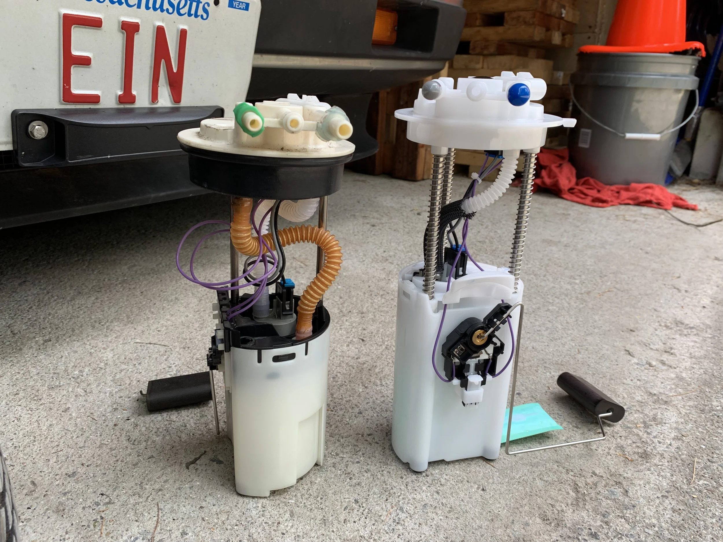
The Tahoe pump (left) and DeLorean pump (right). Note the position of the sender arm, and the difference in height. Otherwise they’re pretty much the same.
Another view of the two pumps, showing the height difference more clearly. Both pumps fit properly in the tank.
The maximum extent of the sender arm, indicating when the tank is full. The Tahoe one is too high, and the arm needs to be bent to account for it.
Using a vice to bend the arm. I also used pliers to squeeze sharp curve further (visible below the vice jaws), and bent the again near the joint where my hand is so that it sat properly at the bottom of the tank.
The sender arm after flipping it so that its variable resistor reads the same way the DeLorean one does.
The arms both sitting at about the same height. I could have spent more time bending the arm to make it more horizontal, but it just needs to be “good enough”, and if I bend it too much I risk breaking it.
From the top you can clearly see how the sender arms point in different directions, necessitating a different orientation in the tank to clear the sides and the ground wire.
There’s a plastic alignment tab on the Tahoe pump that interferes with the clamp and needs to be removed (that, or you can notch the tank lip, but I decided to just saw it off).
Final installation, save for the electronically connection, with the sender arm aiming towards the back of the tank. Note that the access panel does not fit in this configuration. Also note that there is a ground wire running along the driver’s side of the tank, so the arm can’t point hat way either.
The Tahoe sender re-oriented in a manner similar to the DMCH unit. Two pieces of plastic needed to be clipped off of the top of the sender so that the access panel could be re-installed.
Final final installation, with the sender arm pointing more in the direction that the DMCH one would, and the the excess bits of plastic clipped off so the the access cover mostly seats properly.
Sway Bar Bolt
I had been hearing a “clunk” from the front left of my car sometimes, and the steering was a little less stable than expected, but not horribly so. While pointing out the tow hooks for the tow truck driver, I noticed that one of the bolts was missing from my sway bar (aka anti-roll bar), and the bracket was bent back. That would explain the problem quite easily.
It seems that I’d used M11 bolts when the original M10 bolts wouldn’t fit. This one was so bad that an M11 wouldn’t fit either, but an M12 was too big. Luckily I had an M10 TimeCert kit, and was able to install the threaded insert and a new M10 bolt. I had to bend the bracket back with a pry bar and a vice. This fix is holding securely, the clunk is gone and the steering feels a bit more stable.
The missing bolt and bent bracket.
Un-bending the bracket with a vice and a pry bar.
A new M10 bolt inside the newly repaired hole with the restored bracket.
Coolant Temperature Issues
After a bit of driving with my new water pump, I noticed engine temperatures getting close to 220. This is the upper edge of what I consider to be safe, and 20 degrees below the red line. The cooling fans come on somewhere around 207 degrees and turn off again around 196 degrees. In my EFI-converted car, this is controlled by MegaSquirt via a sensor on the water pump.
The interesting thing is that TunerStudio reports that the temperature was only going up to the 202 or when driving down the highway. At a stop it would get over 207, at which point the fans kicked on and brought it back down to 196 as expected.
Being rather concerned about this, I bled the system at the radiator. I have DeLorean Parts Northwest’s Wings-B-Cool Radiator Bleeder Kit. This adds a valve to the radiator that can be turned by hand to let the air out of the system, and is much easier than disconnecting the hose and getting hot coolant all over you. I bled the system five times over a period of days, each time hearing the hiss of steam before hot coolant came out. Once the bubbles had mostly stopped, I closed the valve. Each bleed seemed to help bring the coolant temperature down on subsequent drives, although it was also getting a little cooler outside each day, which would have had an affect as well.
An important detail I forgot was to refill the coolant system after bleeding it. My coolant level had gotten low enough that it was sucking a little air in from the bottom hose. It should be filled roughly half way. I also bought a replacement 16 pound coolant cap; 15 pounds is the correct pressure, but an RC15 cross-references to
The temperature gauge uses a sender mounted on the back of the passenger side cylinder head. It’s possible (and likely) that I’m getting different readings between this and the water pump mounted sender used by MegaSquirt simply because they’re reading the temperature at different locations. A question about this on DMCTalk led me to use an IR thermometer to test the temperatures at the coolant hoses. Testing the pipe that normally has the otterstat in it was recommended, but the shiny surface read only 170 degrees, which the black hoses came up with between 190 and 195 degrees — around the same as what TunerStudio was reading from MegaSquirt. The thread also had warnings about how the stock gauges are more suggestions than exact readings.
It’s important to note that I did not calibrate the coolant or air temperature senders before hooking them up to MegaSquirt. I believe they are standard GM units, so the default curves in MegaSquirt should be correct, but I went ahead and calibrated the coolant sender, as per the instructions on DIYAutotune. It’s pretty simple: put the sender in boiling water and read the temperature with a thermometer and the resistance with an ohm meter. Repeat with ice water, then again at ambient temperature. These three values are plugged into the temperature sender calibration fields in TunerStudio. My results were fairly close to the default GM setting, which resulted in about 5 degrees Fahrenheit cooler readings across the board, although I wasn't entirely sure I did the boiling test that well. I decided to revert back to the GM preset and possibly have the gauge read a little high instead of a little low.
I then did about 20 minutes of highway driving and 10 minutes of surface street driving. At highway speeds of around 70 MPH, the gauge in TunerStudio would read between 198 and 202, while the stock gauge would read about 3/4 of the way between the first unlabeled mark and 220. This was on a sunny 81 degree day. The temperature only went higher when I turned off the A/C and was stuck behind a truck doing 20 MPH on surface streets. It got up to about 205 before I turned the A/C back on, eventually reaching 207 before the fans brought it back down. Once free of the truck and back up to 30-40 MPH, the engine temperature went back down to 198 and stayed there for the rest of the drive home.
So it looks like my car just likes to run at 198-202 in TunerStudio, and a bit under the 220 mark on the stock gauge. As long as it doesn’t rise high enough to cause problems, I can live with that.
Temperature gauge at highway speed (note that the speedometer isn’t working here, which is why it reads zero).
The temperature gauge in TunerStudio (top right), also at highway speed. After bleeding the system the temperature did read a bit lower.
Locations where I tested the temperature with a contactless IR thermometer. The low 175 reading was likely due to the shiny metal pipe, as it is very unlikely that the coolant temperature was actually that low. The other readings are close to what TunerStudio showed.
Using a thermometer, an ohm meter and a pot of boiling water to calibrate the high end of the coolant temperature sender. In this picture the sender is still warming up. Only the end of the sender is in the water, not the whole thing. Also, the meat thermometer would read differently depending on how much of it was in the water, so I’m not sure how well I did my calibration here. The ice water and room temperature readings were much easier (I forgot to take pictures of those).
My calibrated coolant temperature settings in TunerStudio, which reads about 5 degrees lower than the GM preset.