Converting the A/C from R12 to R134a: Parts and Disassembly
Joe Angell
A few years back I brought my car to an A/C shop to recharge the R12. 3 months later, it was empty, implying a leak in the system. The shop filled it again and put in dye, but was unable to locate the leak. The best guess was a problem at the evaporator.
I had opened the A/C system to air when I'd done my 3.0L swap. I needed a new compressor that would work with the 3.0L's serpentine belt, and it would probably be a good idea to replace the 37+ year old A/C hoses with new ones. Also, two of the four mounting tabs on the condenser were broken, although it seemed to staying put so far. I also have an early car, which is missing some of the upgrades present on later vehicles, most notably a high-pressure switch.
All of this meant that this was probably a good time to update the entire A/C system, removing every component and replacing it with new parts and converting to R134a refrigerant.
Parts
In short, basically everything. I would also be converting to the later production configuration, which runs the lines a little differently and adds an adaptor and a high-pressure switch.
All three hoses between the compressor, condenser and evaporator (100750, 100748, and 110525), built for R134a
Condenser with accumulator/drier, orifice tube and O-rings (106327)
Evaporator core (101272). There's a kit that includes the accumulator/drier, orifice tube and O-rings (K101272) for an extra $100, but I'll already have those from condenser kit.
Heater core (101271), which is more of a "while I'm in there" part
3.0L-compatible A/C compressor, mostly for the serpentine belt and for mounting it to the valve cover.
3.0L A/C compressor mounting solution
Low pressure switch (100744)
High pressure switch (106917)
High pressure switch harness (110526), as the early VINs didn't include a high pressure switch at all
Pressure relief LVL (106918)
Condensor adaptor (110527)
Most of the parts are available from store.delorean.com, and most are compatible with R134, but not everything.
The DeLorean hoses are only R12-compatible, though, but DMC MW was able to make some R134 hoses for me. DeLorean Performance Industries and John Hervey both sell their own R134 split hoses, but I decided to go with DMC MW and single-piece hoses.
The A/C compressor is just an off-the-shelf aftermarket compressor. The stock DeLorean compressor would technically work, but V-belt pulley isn't compatible with the serpentine belt of the 3.0L engine, and the mounts are completely different. It was simpler just to buy a compatible compressor.
Mounting the compressor is another story. My engine didn't come with the compressor or its brackets. eBay didn't turn up anything, either. And the 2.8L brackets don't fit on the 3.0L valve cover. At worst, I could just fabricate my own brackets. But luckily, none of that was necessary -- Farrar had done this conversion himself, and found that the compressor bolts right to valve covers, although he did need some spacers so that the A/C lines would clear the oil filler. That saves me a lot of trouble.
I asked about the compressor on DMCTalk.org, and someone pointed out that Four Seasons has a product selector that includes the Eagle Premier. It suggests the 58555 for a new compressor, and 57555 for a rebuilt one. Both are R134a ready. Summit Racing had the best prices, at a little under $300 shipped for the new one and about $225 for the rebuilt one, although the $25 core requirement for the rebuilt meant that it was really $250, as I had no core to send back. I decided to opt for the new one, but I probably should have just saved the $50 and gone with the rebuild. I likely could have even bought a $100 shipped rebuild of the original compressor and drained the oil.
The condenser adaptor is a special addition that provides a way to hook up the pressure relief valve and the high pressure switch, which are not on the early cars (although there is a plug for the high pressure switch, oddly enough). Later cars had a unique hose end with connections for these at the evaporator, but that is no longer available. The adaptor connects at the condenser side of the hose. It took me a while to realize that, since there is no documentation for this block, and it's not in the parts or workshop manuals.
I also needed a few new tools:
Manifold and gauges
Vacuum pump
Large wrenches for the hoses (22mm, 27mm and 32mm)
I bought the manifold, gauges and vacuum pump together on Amazon for about $100. The wrenches I was able to find at Home Depot.
For the R134a and compressor oil, I just picked them up locally, since they're readily available. I also got a green O-ring kit, since I didn't have enough with what came from DMC.
Reference
I found a few good pages for doing this work. Beyond the Workshop Manual section N, I found some pages on DMCTalk.org that discussed split lines vs. single lines and some other tips.
One of the most useful pages is this one that details rejuvenating an R12 system. It explains how the DeLorean's stock R12 system works, and provides a lot of detail about removing and replacing parts. Unfortunately, all the images are broken, so it's a text-only reference.
Removing the Old System
I decided to start by removing the hoses. This picture from the Workshop Manual, page N:08:03, is particularly handy, as it shows exactly what wrenches you need to remove them.
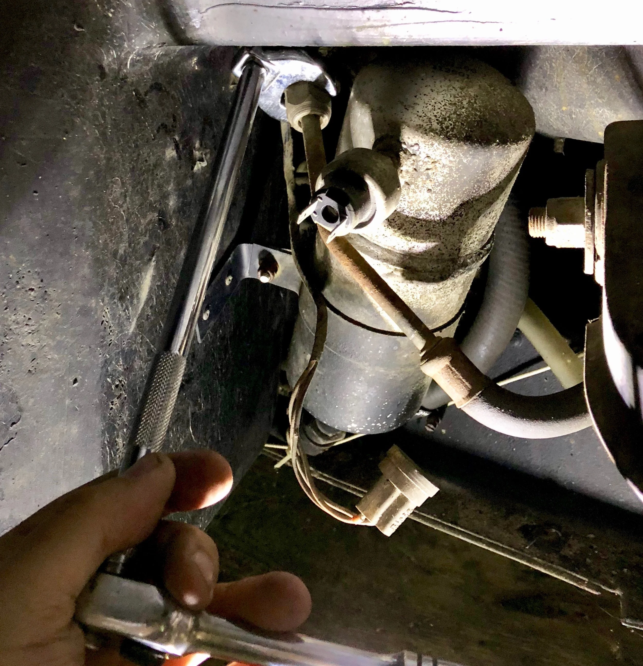
The compressor was already out, and those ends of the hoses were already disconnected, so I went to the other end, starting with evaporator. This required raising the front of the car and removing the passenger side front tire. With that out of the way, the accumulator/drier and related hoses are clearly visible.
A/C components behind the passenger side front wheel.
Hose from the Condenser to the Evaporator, Evaporator End
The space is annoyingly cramped for wrenches. Eventually I'd need to open the access panel in the trunk, but for now I used a 22mm crows foot to turn the nut on the hose between the condenser and the evaporator, which came free with remarkably little force -- there was no need to put a wrench on the nut on the evaporator side. I unplugged the pressure switch first (it just pulls out from the accumulator) to make more room for the wrench.
Unfortunately, that's as easy as it got -- the hose would not separate from the evaporator. Since I was replacing everything, I could have just cut it out, but I really wanted to figure out how to get it apart. I tried a pry bar, a heat gun, and finally a MAP torch. Using a torch is tricky, as the fuel lines and tank are very close by.
I left it for the week after liberally hosing down all of the remaining connections with PB Blaster (I often use Kroil, but that comes in a drip can, and these connections are above and needed to be sprayed). When I came back, I was able to clamp onto the hose with vice grips and twist that hose, and it moved. A couple of twists, and I was finally able to pull it free.
Disconnecting the line from the evaporator to the condenser with a 22mm crows foot wrench.
PB Blaster and Kroil, which I used to help break the corrosion on the hose ends.
The very stubborn connection that refused to pull free.
The rather dirty ends of the hose that runs between the evaporator and the condenser.
Hose from the Compressor to Accumulator, Accumulator End
There's a hose that runs from the accumulator that leads to the compressor. On early VINs line mine, this hose exits the bottom of the compressor, but it's positioned differently on later cars. First I needed some bigger wrenches. Luckily, Home Depot miraculously had the needed 22mm (for the condenser), 32mm and 27mm wrenches.
The problem here was getting enough leverage to turn the wrenches. After letting the penetrating oil sit for a week, I put on the two wrenches and fit them both into the jaws of an adjustable wrench. This gave me the leverage to squeeze the wrenches together, which broke the nuts free.
At this point I could remove the hose, since I had already disconnected the compressor end long ago. To keep things simple, I cut the connector off and pulled it through the car, since I wouldn't be using it again anyway. I probably could have just cut it at the connector, but this made it easier to get through.
Using two wrenches and an adjustable wrench to get enough leverage to separate the lower hose.
The lower hose separated from the accumulator.
Hose from the Condenser to the Evaporator, Evaporator End
At the condenser, I started by removing the old Special T Auto fan cowling, which meant removing the line of nuts along the bottom of the fascia with an M10 socket.
With that out of the way, I used my existing 19mm and the new 22mm wrenches to break the lower condenser hose free. Even without penetrating oil, this wound up not being overly difficult. Once disconnected, I was able to remove the hose from the car completely.
The upper condenser line provide a bit more challenging, and I couldn't get the giant wrenches up there. I decided to drop the radiator and condenser first.
Dropping the Radiator and Condenser
I had replaced the radiator maybe a year before taking the car off the road for the engine swap, so I was familiar with this procedure. First I took off the driver's side tire, making it much easier to get to the brackets on that side.
I started by draining the radiator. I removed the hose clamp on the bottom, and placed a bottle with a funnel under the connection. I found that I could lay a pry bar on its side to leverage the short hose off of the radiator, which poured about a quarter gallon of coolant into the bottle. I also disconnected the bleed line from its pipe, which was done by removing the hose clamp and twisting while pulling the hose to release it from the pipe.
The sway bar is sort of in the way, so its bracket is removed with two bolts on each side via a 16mm socket. The sway bar itself doesn't have to come out, just the bracket for the bushings. You might be able to leave the brackets in as well, but I decided to remove them to give myself a little more space.
Before I went any further, I unplugged the cooling fans. It would be pretty annoying to have to replace the wiring because I forgot those.
Next the radiator brackets then need to come out, along with the angled braces. Since these are the only thing holding the radiator up, it's a good idea to place a jack under it to take the weight. Once the brackets are removed, the jack can be slowly lowered to drop the radiator.
Each bracket is secured to the radiator with a large nut that requires a 16mm socket to remove. You can probably just leave this part alone, though, since the radiator sits on the bracket -- it's the bracket itself that has to be removed from the car. A 13mm socket can be used to remove the one bolt on the side and two from the top of each bracket and the front frame extension. The top two also secure the horn mounts to the frame, so the horns will be unplugged and removed as well.
The angled braces run from the top of the radiator to the top of the front frame extension, and use a 13mm socket. For whatever reason, the one on my passenger side wouldn't line up, so it wasn't bolted in. The driver's side one is also used a ground, and has a bundle of wires on its bolt. My new ground bus also ran to this same bolt. I didn't actually remove the angled braces -- I just took out the bolt, then pushed them to the side so that they would clear the front frame extension.
Draining the radiator into a bottle.
The bolts that are removed for the radiator bracket. The angled brace can be seen along the top and left of the photo as well. The large pipe in the foreground is the radiator hose.
Driver's side showing the angled brace and the ground wires attached to its bolt, as well as the upper compressor and radiator hoses.
I also removed the radiator hose from this side. I again used a pry bar to lever it off, which eventually worked.
The condenser upper hose was another story. I'm pretty sure I was just twisting the aluminum instead of loosening the nut. I finally squeezed my fuel line cutters over the hose and cut it. Both the condenser and hose are being replaced, so it wasn't worth spending the time to remove it.
Now that everything was disconnected I was able to carefully lower the radiator with the jack. The fan shrouds got caught up against the front frame extension, but that was easily corrected. I found that the compressor was only being held on to the radiator by one of its four brackets, and that one was just about to fail. The nuts were rusted solid, so I used an angle grinder to cut the bracket remnants from the radiator.
One of the mounts for the radiator was also slightly broken on one side. It wasn't a big deal, since the radiator sits on the bracket and it won't fall out if the bracket breaks, but I decide to try welding it back into place. I removed the fans from radiator, which requires a 7mm wrench for the angled braces and a 10mm socket for the others. I only really removed them because I didn't want to melt them with the oxyacetylene.
My novice welding skills caused some problems here. The bracket needed to be pushed against the radiator body, but the thinner bracket metal melted away before I could get the body hot enough to liquify. There was no place to the bracket down, either. I tried letting it hover a little and using filler rod to fill the gap, but that led to a weak weld that broke easily. I really needed to hold the bracket down and hold the filler rod at the same time.
The radiator partially dropped. The upper compressor hose is the only thing keeping it in place.
Fuel line cutters used to cut off the upper condenser line, visible sticking out from behind the radiator.
Grinding the broken condenser brackets off of the radiator.
The radiator, condenser and fans removed from the car. The angled braces are still attached to the top of the radiator.
Heater Core Hoses, and Separating the Evaporator to Accumulator
I went back to the trunk to disconnect the accumulator from the evaporator. This meant removing some more things I'd just re-installed: first, the aftermarket anti-sway bar mounted to the shock towers had to come out with a 17mm socket. I could then remove the spare tire, roll back the carpet, and take out the Philips screws holding the fuel tank access cover in place.
The evaporator, accumulator and heater core lines were now clearly visible next to the fuel tank. Since I was replacing the heater core and the hoses were in the way, I dealt with them first. After fighting to get them off the core, I googled for "hose pliers" and discovered that I already had a set as part of a long-handled pliers set I'd bought some time ago. These pliers have a "C" like shape that forms a circle when closed. The ones I had were a little small, but allowed me to grab the hose where the hose clamp had been and twist to break it free from the evaporator. I was then able to pull it off and cause coolant to pour all over the frame and floor.
To keep from leaking more coolant everywhere, I slide a large, short bolt into the end of each coolant hose and clamped it down. This effectively capped the lines and meant that I didn't have to worry about keeping them upright anymore.
To separate the evaporator from the accumulator, I only needed the 27mm wrench. The 32mm attaches works on the nut built into the accumulator, but the penetrating oil did its job well, and the 27mm was all I needed to get the evaporator's nut free. I had to turn the wrench, then flip it over and turn it again, repeating this until it was free due to the limited space.
The last thing to remove was the accumulator itself. The accumulator bracket is riveted to the body, and warps around the accumulator to clamp it with a single bolt. A 10m socket and 10mm wrench got them apart easily, and I was finally able to remove the accumulator.
The low pressure switch is attached to the side of the accumulator. This was finger loose -- it's a good bet this is actually where my refrigerant leak was coming from. Oh well; I wanted to update the system anyway...
The care raised high enough to work under it, with the front tires removed.
What is where behind the trunk access cover. The accumulator and evaporator need to be separated, and the heater hoses need to be disconnected.
The heater coolant lines capped with bolts hose-clamped in place.
The empty space where the accumulator used to be.
The original accumulator finally freed from the car, with the lower pressure switch still mounted to the right side.
Fuel Tank Shield
This part probably doesn't have to come out, but I lowered it anyway. The heater lines run under the shield, but the A/C lines run along the outside of the frame next to the body. There are bolts running along two edges that need a 13mm socket. If you don't take them out, you should at least loosen them, as the captive nuts they screw into will bind the A/C lines. All of these came out very easily for me.
The ones along the front of the shield require a 10mm socket. This was a mess -- only one came out on its own. I sheered the heads off of all but one of the remaining bolts, with the last one being worn away so much that I couldn't get a wrench on it. I wound up taking the head off with an angle grinder.
This wasn't enough, though, as the shield sits above that piece of metal, not below it, so the remains of the bolts were keeping the shield in place. Since I didn't really need access here, I just cleaned up debris that had collected and bolted it back up. The broken bolts along the front edge would hold the shield in place just fine; I had no worries about it falling down. At worst there might be a little rattle.
Most interesting was the two cut copper lines zip-tied to one of the heater hoses. The lines don't lead anywhere -- it's just a single pipe bent into a loop. The best guess on DMCTalk.org is that this was an aftermarket attempt to create a transmission cooler, as the copper lines are running along the colder coolant line. I vaguely remember having DMC CA install this 15 years or so ago, and eventually replaced it with PJ Grady's heat exchangers. I just cut the zip ties and removed the line.
I re-installed the shield with fourteen new stainless steel M8 bolts and washers, plus one M6 along for the single bolt I didn't break along front edge.
The fuel tank shield under the car. I've already removed a number of bolts from the driver's side.
A pair of copper lines zip-tied to the coolant return pipe were likely an attempt at a transmission cooler.
This is as much as I could drop the shield, due to the broken bolts along the front. This shield collects a lot of debris as well.
Compressor Hoses
The very last thing I removed were the hoses that ran the length of the car, from the compressor to the accumulator and condenser. With all of the components out of the way, I just had to pull them though.
At this point a friend of mine who actually knows what he's doing came to visit to help me with the rest of the A/C system. We'll just call him The Mechanic (but his name's Dave), and has a day job fixing classic cars. He did the actual removal of the lines without cutting them (I was just going to cut them). It took some effort, but he got them out. There were a few zip ties to remove, but that was about it. Removing the fuel tank plate wasn't necessary, but loosing some of the screws was useful, since they poke through their captive bolts enough to bind the A/C lines lines.
Evaporator Box
This is the part that everyone really seems to hate, but I didn't find it too hard -- once I knew how to do it properly. I removed extra screws I didn't need to, and didn't remove enough in other cases, then tried to pry the box and broke it.
The evaporator box reaches from the blower motor all the way to the driver's side of the center stack, and contains the heater core and evaporator. There are only two points where the box is secured to the car:
A golden bracket behind the center stack, with two hex screws and two nuts.
Three nuts behind the recirculation vent behind the blower motor.
Of course, to get to the bracket you have to take out the center stack. To get to the recirculation vent ones, you have to remove the passenger kneepad, the glove box and the recirculation vent. And you probably want to remove the blower motor just to reduce the amount of weight while you're pulling the box out of the car. And the passenger seat so that it's easier to access all of these bolts.
Passenger Seat
Crawl under the car and remove the four locknuts holding the passenger seat into the car with a 10mm socket. You can then lift the seat out from the passenger side door.
Passenger Side Carpet
There's likely going to be coolant in the heater core, so you'll want to pull up the carpet on the passenger side floor. It's not tacked down, so it should come up pretty easily. I just folded mine back to where the seat would have been.
Center Console
This is the arm rest between the seats that the power window controls are in, and which runs up over the center stack. Mine was already out. You first have to remove the shifter knob and the shift plate, unplug the clock and remove the shifter light bulb.
Next there are three pairs of nuts holding the trim to the body, which require a 10mm socket.. The first is at the base of the center stack, the second just forward of the switches, and the third under the bin at the back of the arm rest. You then have to unplug the window and defroster switches, and the cigarette lighter. Finally, you can just lift the console out.
Center Stack
The center stack is where the radio and climate controls live, and behind it is the golden bracket you need to remove. After the center console is out, this isn't really that hard to remove, and it's a lot easier to get at the bracket, although you can probably reach around it if you want to go through the effort.
First, you have to remove the radio. Exactly how you do this depends on your radio. Mine is aftermarket, and simply pulled out, after which I disconnected the harness, antenna, and line in cables I was using for my iPhone.
Next, the climate controls come out. There are a couple of obvious but very small screws that secure a couple of the dials to the face plate. The light bulbs simply pull out of the back. The other switches and dials are unplugged from behind, then pulled out of the front. I labeled all of the wires before pulling anything out, re-connected the various buttons and switches to their plugs, and left them lying behind the stack.
Finally, the stack frame itself is removed with two Philips screws along the top edge. Before you lift it out, remove the ground bundle on the right side of the frame with a pair of 7mm wrenches. You can take out the two rubber adaptors between the air distributor box and the vents as well.
The yellow arrows point to the two screws that hold the center stack to the dashboard.
The red-handled bit driver is on the ground bundle that needs too be disconnected to remove the center stack frame.
The mess of wires that is left after removing the center stack.
Bottom Bracket
Below the air distributor on the face of the evaporator box is a golden metal bracket. This secures the evaporator box to the frame. The two hex-head screws on either end can be removed with either a 1/4" or 8mm socket (for whatever reason, I had an odd mix of 1/4", 8mm and 7mm hardware here). The nylock nuts come out with a 10mm socket, after which you can remove the entire bracket. The Philips screw in the middle doesn't need to come out, since it's one of four that connects the distributor box to the evaporator box.
The bracket below the air distributor that secures the box to the frame. You need to remove the two screws on the box, and the two nuts on bottom, as removing the entire bracket makes things much easier. The center screw is not removed here.
Passenger Kneepad
Everything you need to get to sits behind the kneepad, and it blocks the removal of the evaporator box itself. This is held in with four bolts and removed with a 10mm wrench. You'll also be disconnecting the duct from the air distribution box by simply pulling it free.
Glove Box
The glove box needs to come out in order to make enough room for the evaporator box. First remove four Philips screws that secure hinges for the cover. Then use a pair of 10mm wrenches to remove the two nuts and bolts for the latch and remove that. Next unscrew the large retaining nut holding the light into the side of the box, and pull the assembly out from inside the box, separating it from the wiring on the outside of the box. Finally, remove the four Philips screws running around the top of the glove box, and pull the entire box upward to remove it from the car.
The glove box removed from he car. There are four screws around the edge, two screws on each hinge, two bolts for the latch, and the light through the side.
After removing the center stack, glove box and kneepad.
Defrost Vent Duct
The defrost vent duct sits on the top of the air distributor. The distributor has ports for the driver's side and passenger side door vents on the sides, the foot vents on the bottom, the defrost vent on the top, and two ducts facing towards the back of the car for the center centers.
The defrost vent ducting is held on with two Philips screws on the left side of the top of distributor. You should be able to reach these pretty easily. Once unscrewed, you can tip the top of the ducting towards the front of the car and, with a little wiggling, pull it down and out towards the back of the car to remove it.
The position of the defrost vent under the dash. The two screws on the face come out, and then it can be tilted out from under the dash. The air distributor is removed in this picture, as is the duct that goes from the distributor to the vent. The drawings on the box are for a later experiment, and indicate safe areas to cut the box and the default location of the defrost flap.
Driver's Side Duct
This duct is simply pulled out of the duct air distributor box. You may need to loosen the duct's bracket, which is a golden piece of metal behind the steering column. Just use a Phillips screwdriver to remove one or both of the screws.
Disconnect the driver's side ducting from the air distributor box.
Vacuum Lines
There are three vacuum actuators on the left side of the box. I disconnected them from the actuators themselves (they simply pull off), although it can be difficult to reconnect them once the box is back in the car, especially the one in the back. You may want to disconnect them from the mode switch instead.
The two side vacuum actuators are marked here; the third is behind the box. Disconnect the vacuum lines from these three, or from the mode switch. The corrugated tube on the top of the distributor goes to the now-removed defrost vent.
Another view of the two side actuators. The leftmost arrow points to where the rear actuator is hidden.
Recirculation Vent Flap
There are three nuts we need to remove behind the recirculation vent flap, which means it has to come out. This sits just above the blower motor. There are four Philips screws holding the flap in place, although my car was missing the bottom one for some reason. Once the screws are out, you can finagle the closed flap past the evaporator box by sliding it to the right. Just make sure the flap is closed all the way first. Disconnect the vacuum line and set the assembly aside.
You can now reach into the opening to the air intake behind the duct and remove the three nylock nuts with a 7mm socket that secure the evaporator box to the body. Water can drain into this area, and although the epoxy coating on the metal here was fine, the nuts were rusted. Two of them spun freely on their studs, and eventually pulled free (with the studs) from the box when I removed it (you won't be able to pull them up; just wait until you pull the box down), but I was able to get one out. I later cut the nuts off with an angle grinder, then cut the stud posts out of the box and replaced them with a simple nut-and-bot arrangement. The only down side of using bolts like this is that you must drop the blower motor to remove the box in the future, but you're probably going to do that anyway.
With the glove box and kneepad removed, the recirculation vent flap can be seen through the opening.

The removed vent, showing the four screw holes around the plastic frame that secure it to the air intake.
These three nylocks (one hidden on the left) are what hold the right of the box to the body.
Blower Motor
If all the nuts came off the studs behind the recirculation vent flap, you can probably leave the blower motor where it is. However, it's pretty heavy, so you might want to take it out anyway just to make the rest of the box lighter.
There are a total of eight (8) hex head screws that need to be removed for the blower motor and the resistor. The easiest way to reach this is to lay on your back with your legs over the parcel shelf and your head under the motor. First, unplug the ground wires and the power wire from the motor, and unplug the resistor's four-pin connector.
The blower motor is held in place with six hex-head machine screws, and the resistor with two more. Both should be removed. I found this easiest with a 7mm socket (or 8mm; I forget now) on a bit driver, or with a power screwdriver fitted with that socket. The motor is heavy, so be careful not to drop it when removing it. I took the rubber vent hose out with the motor as well, but left it attached to the motor.
The power wire (left), ground wires (left bottom) and resistor connector (right) are highlighted here. The blue hex nuts around the perimeter of the motor (six total, left) need to come out, as well as the two on the resistor (right).
The dropped blower motor.
Evaporator/Heater Core Pipe Rubber Boot
I'm not sure you have to remove this, and honestly it's a real pain to get back in, but you probably should. This boot is accessed from fuel tank access panel in the trunk, and keeps wind and debris from coming into the car from where the heater core and evaporator lines poke through the firewall. The low pressure switch and high pressure switch wires also go through here. If you want to pull those switches through, you'll need to remove the boot. If not, you can probably just cut the wires and attach connectors. We removed the boot with some picks.
Drain Tube
Underneath the car is the evaporator drain tube, which lets the condensation from the air conditioning system leave the car as water. Simply pull this out from the passenger side wheel well area near the firewall to remove it.
Cold/Hot Split Flap Cable
This cable goes to the flap on the bottom of the box, and controls how much hot air vs. cold are is running through the vents. Since I'd taken out the center stack, the knob was already free, so I saw no reason to disconnect the cable -- I just took the entire unit with me when I removed the box.
Actually Remove the Box
Finally, everything is out of the way and you can remove the box itself. It first needs to be lifted up a bit so that the drain plug clears the frame. It's only an inch or so. This is why you have to take out the defrost duct, to get some space above the box to lift it into. We didn't, and we tried to use a pry bar to bend it up, which shattered the box around the drain, and which we then had to repair. After removing the duct it moved much more easily.
You can now pull it towards you as you feed the heater core and evaporator pipes through the firewall. Be sure to feed the pressure switch wires through if you weren't able to disconnect them or didn't want to cut them, just so you can move the harness out of the way.
At this point, you should be able to pull the entire box towards the passenger side, by tilting the passenger side towards you as you rotate it away from the center of the car. It should come out pretty easily once you get the evaporator and heater core lines through the firewall, anyway, and if you can avoid the wiring harness that is now hanging in front of it.
You know know how to take apart the majority of the front cabin. We actually did this wrong, trying to remove the evaporator box screws and separating the right half of the box from the left half while in the car. This is a huge pain. It's simpler to take them out as a single unit. I have no idea how we'd have gotten the box back together inside the car (although it has been done).
What it looks like when removing the entire box. This is actually us re-isntalling it, since we took it apart in multiple pieces to get it out, which is definitely not something I'd recommend.
The complete box out of the car and lying on the garage floor. This is actually after re-assembling it with a new evaporator and heater core, as I don't have any pictures of the box before disassembly.
Disassembling the Box
Now you can take the box apart, which is how you get to the evaporator and heater core.
Air Distributor
The first thing I did was remove the air distributor. It might not need to be removed, but it does strip off some weight, and makes it easier to replace the foam on the doors behind it. This is held on by four screws with three different heads for no apparent reason.
Two hex screws with large washers on the right side, removed with a 7mm socket. You can just loosen these, since the box slips behind them with "U" shaped slots.
One Philips screw at the bottom that has to be removed.
One hex screw at on the top left that has to be removed with a 1/4" socket.
You can set the distributor aside.
Splitting the Box
There are seven (7) hex head screws around right side of the box that hold the top and bottom halves together, plus four (4) more that hold the left and right sides together. All of these have to come out using an 8mm socket (or 7mm socket; I forget now). The box should come apart fairly easily, although you may have to remove some caulk strips to separate the three components.
The Evaporator
The evaporator sits in the right side, where the box splits into top and bottom halves. It should lift out quite easily. There was a lot of debris sitting at the bottom of my box, too. There is a screen on one side of the evaporator that should be transferred to the new one, as this helps keep some of the debris off the fins.
The old evaporator core removed from the box. There's a lot of debris on the bottom of the core. The orifice tube can be seen still inside the near pipe.
The Heater Core
This one stumped me for a bit. There is one screw holding a retainer inside the box, which is easily removed with a 7mm wrench. There are also two more screws on the outside of the box, on the opposite end, behind the vacuum actuators. These also come out with a 7mm wrench.
The problem is that the core was still stuck in there. It turns out the core doesn't come out on its own, but the core is on a kind of shelf with the vent flap, and those come out together. Mine wouldn't budge, because the caulk strips were sealing it in place. After a lot of scraping off the caulk and using a heat gun to soften the rest (being careful not to melt the ABS plastic -- a heat gun can very easily do that, and even more easily soften and warp it), we were able to pull it free and remove the core.
After pulling out the tray, there are two more hex screws that hold a bracket that keeps the end of the heater core in the tray. Once those screws are out, you can pull he heater core off of the tray.
How the heater core comes out. After removing the caulking and the two screws on the back end that secure it, you can slide the whole thing forward, removing the split flap and the core as a single unit. The third screw mounts a small bracket between the pipes that holds the core itself in place.
That's it -- everything is disassembled. Now it's time to put it all back together again.