
Double-DIN Radio Install
Joe Angell
NOTE: This is still in-progress. The capacitor to keep the radio on during cranking still needs to be tested more thoroughly, and I need to install the trim around the face of the unit, but otherwise it’s pretty much done. I’ll update this further once the car is actually running again.
As long as I was ripping apart the interior to replace the A/C system, I decided that I'd finally replace the 15 car old Sony head unit with a new double-DIN touch screen unit with Apple CarPlay support.
I decided to go with a Pioneer AVH-2300. This has a DVD player (that I'll never use), Apple CarPlay and Android Auto support via a USB cable, Sirius XM support (which I won't also use), Bluetooth support for both audio and phone calls via an included microphone, an optional backup camera, and a slew of other features.
Removing the Center Stack
The new radio is a double-DIN unit, which means it's twice as tall as the stock radio or the aftermarket single-DIN Sony radio. I would need to make some modifications to the center stack for it to fit, which meant removing it from the car.
This starts with removing the center console. I already had mine out, but basically you start with the shifter knob. For an automatic, that's two Philips screws on either side of the knob to remove the plastic body, then a wrench to remove the nut on the top of the shaft. You can then remove the shifter plates. If you loosen the lock screw, you can pull out the shaft as well.
Next there are six nuts securing the center console trip to the body. A 10mm socket will remove the two up at the front, the two just in front of the window and defrost switches, and the two under the tray in the back. You'll need to remove two Phillips screws to remove the tray to get to the nuts. You'll also remove a bracket under the two middle nuts. After that, the center console will lift right out.
The center stack starts with removing the old radio. How exactly you do this depends on which radio you have; my aftermarket unit just pulled straight out.
Removing the climate controls starts with a screw that removes the face plate, followed by removing some smaller screws on some of the knobs. The buttons pull out, after which you can unplug them from their connectors. The lights pull out from the back.
You can now reach behind and disconnect the rubber adaptors from the center vents.
Finally, there are two Philips screws at the top that secure the rest of the stack frame. With those out, you can lift the frame off the forward studs for the center console. And that's it -- the center stack is out of the car.
What's left after you remove the center stack.
Wiring Up the Harness
The harness was pretty easy to set up with the center stack out of the way. I went wire by wire, cutting a connection from the old harness and soldering the wire onto the new harness. The old radio installer had replaced the original speaker wires, and the Sony harness had the same color coding as the Pioneer harness, so it was fairly simple. I used heat shrink to protect the wires (well, most of them; I would sometimes forget the heat shrink and have to resort to self-fusing tape after the fact).
I tested the harness by resting the radio in the empty space of the center stack, and plugged it in. A fuse popped -- I'd accidentally laid it the metal radio body on the headlight switch wiring and shorted its wiring to ground. After replacing the fuse, I rested the radio on top of a plastic heat shrink tubing box and tried again, and everything worked great. All the speakers had sound as expected,. I plugged a Lightning cable into the USB port and tested CarPlay with my iPhone, and then Bluetooth for good measure, and that worked great too.
Radio Power
Like all other radios, there are two required 12v inputs:
Always-on power for the memory features.
Switched power for the rest of the radio, speakers, etc.
Wires for both are already run to the existing radio, and should be easy to find. However, the switched power is tied to the accessory relay. This is slightly annoying because this isn't powered while cranking the engine (ie: the key is in the "start" position). That makes sense, and is common in pretty much every car -- you want as much power as possible going to the starter. But of course it means the radio turns off while cranking.
This is normally fine, but the Pioneer head unit has a relatively long startup sequence, requiring at least six seconds to get past the "loading" screen, and then the "we're not responsible if you get in an accident messing with the touch screen while driving" screen (which you can either dismiss manually or wait for it to dismiss automatically). It's a bit annoying to have to wait for this to finish after the car has started, especially since old cars like this don't necessarily want to start on the first try.
There are a few options to work around this limitation. You can install a small battery, but that's a bit overkill. You can run a second wire from the start wire to the radio, and use diodes to ensure that only one wire is powering the radio at any given time, but there will likely be a brief period of no power as the key moves from the "run" position to the "start" position, which will reset the radio anyway. A crank-proof power supply is another option, but these are designed to run car computers and are somewhat expensive for just keeping the radio on for a few more seconds.
I decided to go with a solution based on this YouTube video from Stephen Tack. Stephen uses a large (2200 uF) 16v capacitor and a diode as a temporary power source. The capacitor is connected to both the radio's power wire and the car's accessory wire. When the key is turned to "run", it very quickly charges the capacitor. Once the key has moved to the "start" position, the capacitor is no longer being charged, so it starts draining into the radio's power wire (the diode keeps the capacitor from draining back to the rest of the car and other accessories). The radio doesn't use a lot of power, and a capacitor of this size can keep it running for at least 10 seconds, which is hopefully long enough to get the car started.
The only problem with this setup is the radio will stay on for about ten seconds after the car has been turned off, since the capacitor is still powering it. I didn't really like that idea, so I went with a slightly different route.
In my setup, I hooked up two diodes and a capacitor. One of the diodes is connected to the red/white ignition wire, and the other to the light green accessory-switched wire. The diodes ensure that the power only goes to the capacitor and the radio, and that the accessory circuit doesn't charge the ignition circuit and visa versa. The capacitor is only there to provide a very brief amount of power while the key is transitioning from "run" to "start" and back again, and so it can be much smaller than the one Stephen used..
Capacitor wired to the diodes. Note the mark on the capacitor to the ground pin, and the marks on the ends of the diodes towards the capacitor.
The capacitor needs to be at least 16v to handle the roughly 14v car charging system. I used a 47 uF 16v electrolytic capacitor -- much smaller than one Stephen used, but it only needs to provide power for a fraction of a second as the key moves between "run" and "start". It also happened to be the largest 16v capacitor I had on hand.
The diodes need to also be of at least 16v. I used a pair of 1N4001 power diodes. These have a 1.1v drop across them (so, the radio will get 1.1v less than if it was connected directly to the car's power system), but that should be fine, and Stephen didn't seem to have any issues with it. I'm betting the radio runs at 5v internally, and has a voltage regulator that works without an issue above 8v, so we should be good.
The wiring is simple. Note that electrolytic capacitors are polarized, and there is a mark on the body that indicates the negative side and aligns with the short leg. Diodes similarly have to be wired in the correct orientation.
The ground side of the capacitor is wired to ground.
The positive side of the capacitor is wired to both the light green radio wire and to the marked end of the diodes (the mark indicates the direction of current flow, in this case into the capacitor).
The unmarked side of one diode goes to the light green accessory-switched wire from the car. This provides power when the car is running.
The unmarked side of the other diode goes to the red/white ignition wire from the car. This provides power when the car is trying to start.
I tapped the ignition wire under the center console, running a separate wire from it to the capacitor and diodes that I installed behind the radio. I soldered this together, wrapping it all in heat-shrink tubing and self-fusing tape. When I tested it out, everything seemed to work perfectly — the head unit remained powered even in the ignition position, and survived the key moving between run and start. It's quite possible I didn't even need the capacitor, but it didn't hurt to have it.
in the final install I ran an extra wire from the capacitor to the diodes after the leads broke. This also gives me a bit more leeway in fiddling with the wires back ther in the future without as much risk of damaging the wiring.
The tap to the red/white ignition wire on the driver's side harness in the center console.
Everything connected behind the radio, wrapped in blue self-fusing tape.
A Bigger Capacitor
This all worked fine, until I tried it with the starter connected. I used a button in the engine bay to turn the starter, and the radio lost power. This was interesting for two reasons: the capacitor wasn't big enough to keep this from happening, and it had nothing to do with the key position, since I wasn't using the key.
The likely issue was that the starter simply draws too much power to keep the radio on. It's also only an issue as the starter starts spinning up, as the radio came back on soon very soon after the starter started running, even though I was still holding down the button.
The solution was a bigger capacitor. I cut out the capacitor above and ran two longer wires to a new 2200 uf 16v capacitor similar to the one Stephen used. The long wires were terminated with male and female blade connectors, and the capacitor was plugged into those. This makes it easy to test different size capacitors without taking the center stack apart again. The larger completely solved the power-off problem, but kept the radio on for a full five seconds after the car was turned off.
I bought a set of capacitors and tried again. A 1000 uf 16v capacitor provided power for nearly three seconds (pretty much the linear progression you'd expect from halving the size of the capacitor).
Motion Bypass
As a safety feature, certain radio functions aren't available unless you engage the parking brake, then release it, then engage it again. This includes playing DVD video (makes sense; you shouldn't be watching video while driving), managing Bluetooth devices, and a few other settings. A wire is normally run from the handbrake light for this functionality
I have an automatic, and never use the handbrake. While the DVD video lock-out makes sense, I'd like to be able to manage Bluetooth devices while parked without having to fiddle with the the hand brake.
The solution here is a "Motion Bypass", which is a $8 bit of electronics that simulates the electrical signal of cycling the handbrake. You could also do this with a double-throw push button wired up to ground, 12v and the wire from the radio harness, but this bypass does it automatically for you. It does take about 10 seconds to for it to kick in after the radio has powered up, so you will have to wait at least 20 seconds before you can use those features.
The Motion Bypass simply wires to a 12v power source, ground, and the handbrake wire of the radio. That's all there is to it.
Backup Camera
As long as I was doing all this work, I figured I'd install a backup camera. I bought a $30 NTSC camera (there don't seem to be HD cameras using HDMI yet, and the head unit doesn't support them anyway, just old fashioned RCA connections for NTSC or PAL cameras) from Amazon. This particular camera has a 170 degree field of view, and is designed to mount under the lip of the trunk. In my case, it would be just above the license plate, inbetween the two license plate lights. I considered a camera that would fit in the bumper in between my backup sensors, but the DeLorean sits so low that it seemed to make more sense up by the license plate.
The camera I got had two extra wires that you could cut for slightly different behaviors. The first wire would mirror the image, which is useful if you want to install it on the front (the AVH-2330 support a front camera and a rear camera, but my AVH-2300 only supports a rear camera).
Cutting the second wire disables the guide lines. These consist of a red mark, two yellow marks and a green mark. These help you get an idea of how close or far you are from obstacles as you are backing up. The AVH-2300 can also generate these itself, but the one built into the camera is already calibrated, so I stuck with that one for now. The Pioneer's lines are adjustable, of course, and since they're drawn in HD they are much crisper than those burned into the camera's NTSC signal.
To mount the camera, I drilled a hole exactly between the two lights while the fascia was still on the car. I briefly considered mounting it to one side, but then realized that I'd always want the camera's view to be straight backwards. I found the center by measuring with a tape measure from the edge of one license plate light to the other, marking it, then re-measuring from both sides to make sure it was actually the middle. I used successively larger bits until I had a hole big enough for the shaft of the backup camera.
The backup camera installed above the license plate, centered between the lights.
A longer shot showing how the backup camera looks to other drivers.
Removing the Fascia
At this point I was rather familiar with removing the rear fascia. While technically not necessarily, it did make things a little easier as far as running the wires go. It's also way easier to get the nut on the camera.
The fascia is secured with a line of Philips screws along the top edge, seven M6 hex bolts and nuts that require pair of 10mm wrenches, and three nuts on the inside of each tail light opening that holds the sides of the fascia to the body, again requiring a 10mm socket. Each tail light is held in with six black Philips screws.
With all those out of the way, the fascia can be lifted up and back to release it. You can't actually take it off the car without removing the separate backing panel or removing the taillight wiring harness, but that isn't necessary here.
Securing the Camera
The camera just slips into the hole, and then a nut slips down the wire and over the shaft. Once tightened down, the camera is locked in place and looks back as expected.
Wiring
The Pioneer head unit lets you switch to the backup camera at any time, not just when in reverse. To take advantage of this I decided to run a wire from the accessory-switched wire that power the radio to the camera, rather than just using the reverse light for power. I ran this along the passenger side of the car, around the electronics tray in the parcel shelf and past the vacuum reservoir and the charcoal canister (which in my car has been replaced with an air intake). It probably would have been easier to run them through the driver's side, where I had previously drilled a hole for the backup cameras, but I figured I'd give this a try.
I did wind up drilling a hole through the fascia backing for this. I was able to use the grommet for the trunk release cable for some wiring, but you can only fit so much through that.
I soldered the wire to the backup camera's positive, and the ground wire to the ground on the passenger taillight harness, which is also where I'd previously added wiring for the backup sensor and high center stop light.
The harness, all wired up.
Testing the head unit with Bluetooth audio.
I ran the backup camera's RCA cable through to the front of the car, taking the same route as the accessory-switched wire I'd run backward. This cable thoughtfully included an extra, unused wire, which I soldered to the reverse lights part of the passenger side harness, much like I had done for the backup sensors I'd installed long ago. The other end of this wire was soldered to the radio harness. With this setup, when the car is put into reverse, the head unit automatically switches to the backup camera.
The only problem with this setup is that it's a bit hard to completely remove the fascia off now, because the wires are soldered in place. I can unplug the RCA cable from the camera, and I can install blade connectors on the wires when the time comes, so it should be fine.
Hidden Antenna
My early '81 originally had a windshield antenna, but a cracked windshield led me to getting it replaced. Apparently the previous owner didn't think much of the old windshield antenna either, and had a power antenna installed in the distant corner of the driver's side rear quarter panel. For whatever reason, the signal wire used to power external amps or power antennas from the Pioneer unit wouldn't raise the power antenna.
To be honest, I never liked the sight of a power antenna sticking up from the body. At least with the Sony unit it was only visible when using the radio, but the Pioneer powered it whenever the head unit itself had power (since it's also used for an amp). I decided to install a hidden antenna instead.
I bought an amplified window mounted antenna from Amazon, with the intention of mounting under the top louver. I also bought an 8' extension cable to supplement the built-in 7' cable, but that still wasn't enough to reach all the way to louver.
My friend suggested a cleaner solution -- install it above the driver's side taillight in the fascia. This completely hides the antenna and keeps it clear of the steel body in the same way that installing it on the louver would. It will sit a bit lower, but it should be fine.
I ran the new antenna cable through the same hole on the driver's side that I ran the backup camera wiring through. I couldn't reuse the original as it appeared to be directly connected to the power antenna. Somewhat annoyingly, I needed the connector to be on the cabin side of the firewall, which meant that it would again be difficult to remove the rear fascia without pulling the cable back through the grommet. Certainly possible, but a bit of a pain.
The antenna is amplified, which means it has a power connection. I connected its positive wire to the same accessory-switched power wire I was using for the backup camera. There's an optional ground wire (without it, the antenna cable itself is used for ground, I think), but connecting it didn't seem to have any effect on the quality of the radio signal, so I didn't bother. A red LED lights on the antenna shows that the amplifier is on, but that's tough to see due to where I mounted it.
It was a little tough to test the signal strength of the antenna, since at this point the car is still in the garage. It picked up a few stations, which is more than I can stay for the old now-permanently-retracted power antenna. A proper test will have to wait until the car is on the road
I test again with the ground wire clipped to the stainless steel body, and the signal did indeed improve, so I wound up soldering that to the ground in on the passenger side tail light harness.
For mounting, the antenna included some very strong tape to secure it to a window, but I stuck it on top of space above the driver's side taillight. I had to remove it at one point because the LED wasn't on (which meant that it didn't have power), which ruined the tap. I replaced it with equally strong 3M VHB tape.
While I was messing with this, I found that one of the wires had broken from the driver's side taillight, right at the connector. I was able to bend that part of the pin back just enough that I could solder wire to it, which I think soldered to the original wire. I ran a quick test of the lights, and everything was good.
The hidden antenna before installation. Its would be mounted just above the tail light, after running the wires through the driver's side behind the quarter panel. The red LED shows that it is powered and working.
The wiring runs through a hole in the firewall behind the passenger side of the parcel shelf, then through a hole in fascia backing to the antenna.
The repaired wire from the taillight connector.
Fixing the Power Antenna
After having to remove the rear fascia again, I decided to install an extension cable between the hidden antenna and the radio so that I wouldn’t have to snake it through the hole in the firewall again. I don’t necessarily like the extra connections, but it was worth the convenience.
While I was doing this, I decided to pull out the power antenna, and discovered a second wire — the 12v meant to power the antenna. At the end of that wire was half of an inline fuse holder. I never did find the other half. I wound up cutting the holder off and soldering a new one in its place, connecting it to an always-on 12v source. The “always on” bit is to ensure that the antenna will go down when the car is turned off.
A test showed the antenna to be working. I did a signal strength test (again still in the garage) and found that he power antenna did work a bit better than the hidden antenna. However, the Pionneer head unit allows the the power antenna wire to be used for an external amp power on signal as well. This means that the antenna would be up any time the head unit was playing from any source, including Bluetooth or CarPlay. I didn’t want that.
I installed a one foot extension from the back of the radio (yes, yet another connector) so that I could swap the antenna cables easily before I make my final decision. I also installed a simple toggle switch on the power antenna signal line so that I could force it to stay in the down position when I wasn’t using it.
Mic
The mic is designed to be clipped onto the sun visor, but I wanted a cleaner installation. For the time being I left it on the visor, but my eventual plan would involve mounting it somewhere to the dash.
Microphone temporarily clipped to the bottom of the binnacle while putting the interior back together.
Modifying the Stack Frame for the Head Unit
Now that everything was wired up, I had to figure out how to actually mount the radio in the center stack. The original Craig radio was screwed in place through the knobs. Ideally, you wouldn't butcher your center stack, and would buy a doubel-DIN from a third party, or a reproduction from DeLorean. My center stack had already been modified for the single-DIN Sony head unit long ago, so I didn't feel bad about modifying it further.
My intention was to install the double-DIN unit in place of the center vents, and relocate the vents to the top of the dashboard. My dashboard was cracked, so I had no problem cutting it up. My stack frame only had a thin piece of metal between radio and vents, which was simple to clip out with some dikes.
The hole was now much too big for the new radio. The vents are much larger than the radio itself, and the single-DIN hole was cut to hold an installation cage that the radio would slide into. Given the amount of space now present, I didn't think I could use a new double-DIN cage here.
It's also worth noting that this radio requires 5 cm of space above and below it, and some space behind it where its fan is. There was plenty of room above and below where the climate controls are. The back would be trickier, but we'll get to that later.
Building a Bracket
I decided that I'd mount the radio from the sides. I could have used long screws, but I was worried that it wouldn't be secure and would warp the stack frame without something in between. We had an idea of using plastic stock and shaving it down, but I didn't really like that. I decided to weld up some brackets instead.
I bought a piece of slotted angle stock from Home Depot. The slots were mostly so I didn't have to drill a bunch of holes. I cut the stock into short pieces, then stripped off most of the angle, converting it into more of an "L" shape with one long leg and one short leg. I overlapped two of these pieces with the short legs, creating a kind of "Z" shape, and tack-welded them together. The zinc-coated steel made an interesting green flame and a left some residue behind, but the welds were fine. I made one of these for each side, and painted them with POR-15, although spray paint would have been fine.
The brackets were the perfect sized and slipped right between the radio and the sides of the stack frame. I wound up using an angle grinder to merge some of the slots to better line up with the holes in the side of the radio, and use the screws that came with the radio to secure it.
To mount the brackets to the stack frame, I drilled one hole through each side, and ran M6 bolts through them. I elongated the holes into slots so that I could better align the radio with the hole in the front of the stack, and to make it more level. Once tight enough, the head unit wouldn't tilt. I made sure the unit was extended just far enough forwards that the trim plate would sit flush with the radio, and that the motorized face wouldn't get stuck on it.
The design of this bracket means that the only real way to remove the radio from he back of the stack frame, as the brackets won't fit through the front of the frame. This isn't a big deal to me, since removing the center console is old hat now, and the stack can be disconnected and leaned forwards without having to remove all the climate controls.
Welding up the "Z" bracket from cut-down slotted angle stock.
The installed bracket, before cutting longer slots for extra adjustments.
A single bolt through each side holds the head unit and its brackets to the center stack.
The head unit positioned in the center stack.
Face Trim
With the radio positioned within the bracket, I needed a way to hide the ugly holes it was sitting in. Rather than creating a plate from scratch, I bought a pre-cut double-DIN one from Amazon. I cut the left and right sides down to be a bit wider than the stack frame, knowing that he center console would extend into it. I also cut the bottom edge, but left the top edge alone for now, as I didn't quite know how far the center console extended.
To cut the plastic trim, I placed a straight edge (some metal scrap) along the plastic and clamped them together on my table. Then I used a utility knife to repeatedly score the back of the plastic until I was at least half way through it, then slid it to the edge of the table and snapped it off. I had a bit of an uneven edge on the first one, but I'd made it a little too wide and was able to sand it down. The second edge was much better.
Fitting the Center Stack
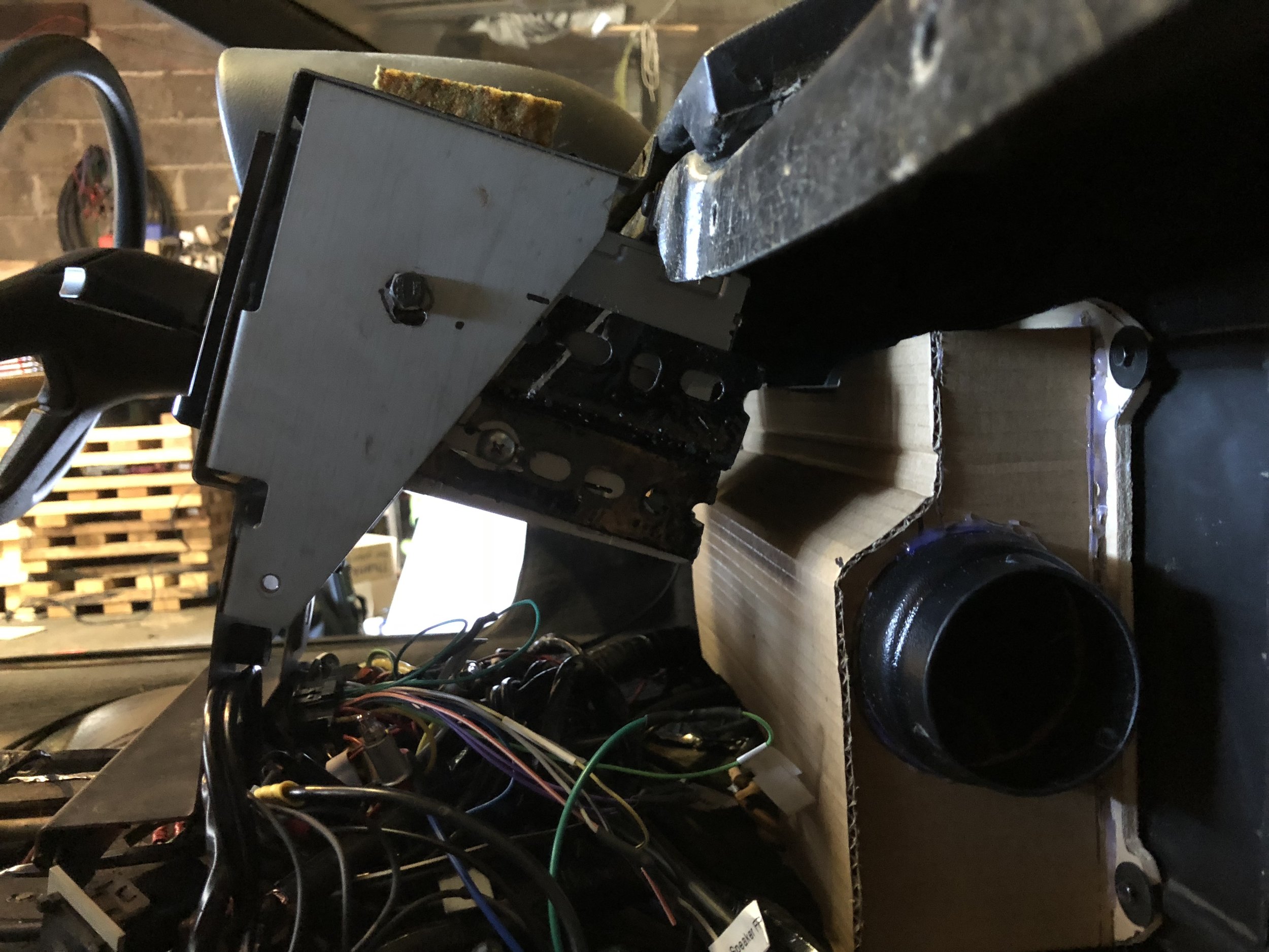
And now the problems begin. I was doing this work while I was replacing the A/C system and had the box out of the car, so I wasn't able to test fit. With the A/C system compete, I was able to test fit the radio.
I had always planned on re-routing the center vents, but the AVH-2300 is much deeper than I expected -- so much so that the stack couldn't reach the screw holes to secure it to the dash. I couldn't simply move the stack forwards, since then the center console wouldn't fit correctly.
After cursing at the car for a bit, I removed the four screws that secure the air distributor box to the evaporator box. The distributor contains the center ducts, the passenger and driver ducts, and a duct that leads to the defrost duct. What I needed to do was remove the center vents entirely. I really didn't want to butcher the original box, so I decided to build my own.
So close, yet so far...
Designing a New Air Distribution Box
I came up with a new design for the box. It would mostly match the old design, but the front would be flat, leaving plenty of room for the radio. I first considered redirecting the center vents upward, with a kind of pod sitting on top of the dash for the vents. In the end, I decided to go with knee pad vents.
The final box has only two ports, one on the driver’s side and one on the passenger side. As mention above, the front vents are removed entirely, although I’d have a total of four vents in the knee pads, so the air flow should be similar. The top duct is also removed. The purpose of this duct is to redirect air from the defroster through the distribution box and out to the door vents, but I can live without those. Also, I won’t be using the door vents anymore. Finally, the vacuum actuator is no longer needed, as there is nothing to actuate. I’d have to cap the vacuum line, but that’s about it.
Building the Box
I started building the box by tracing the mating side of the old box on a piece of plywood. This piece would have the holes for the screws to attach it to the evaporator box, so it needed to be rigid. I first tried cutting it out with a jigsaw, but the thin wood and the vibration from the blade broke it. I tried again with a scroll saw, which worked much better. I cut notches from the two passenger side screws and test fit it in the car before continuing.
To construct a box on top of this mating frame, I used hot glue and cardboard. I simply cut strips of cardboard that were at least as thick as the ducts, then folded and glued it with a hot glue gun as I went. It took only two strips to go all the way around the frame. One final piece of cardboard covers the top of the box.
Before going any further, I test fit this in the car, and positioned the radio to make sure had enough clearance. It worked perfectly.
For the outlets, I bought two Vintage Air 3” to 2.5” adaptors. I traced the 3” side and a hole on each side of the box in about the same location as the door ducts are in the original box. After cutting out roughly round holes, I glued the adaptors in place on the box.
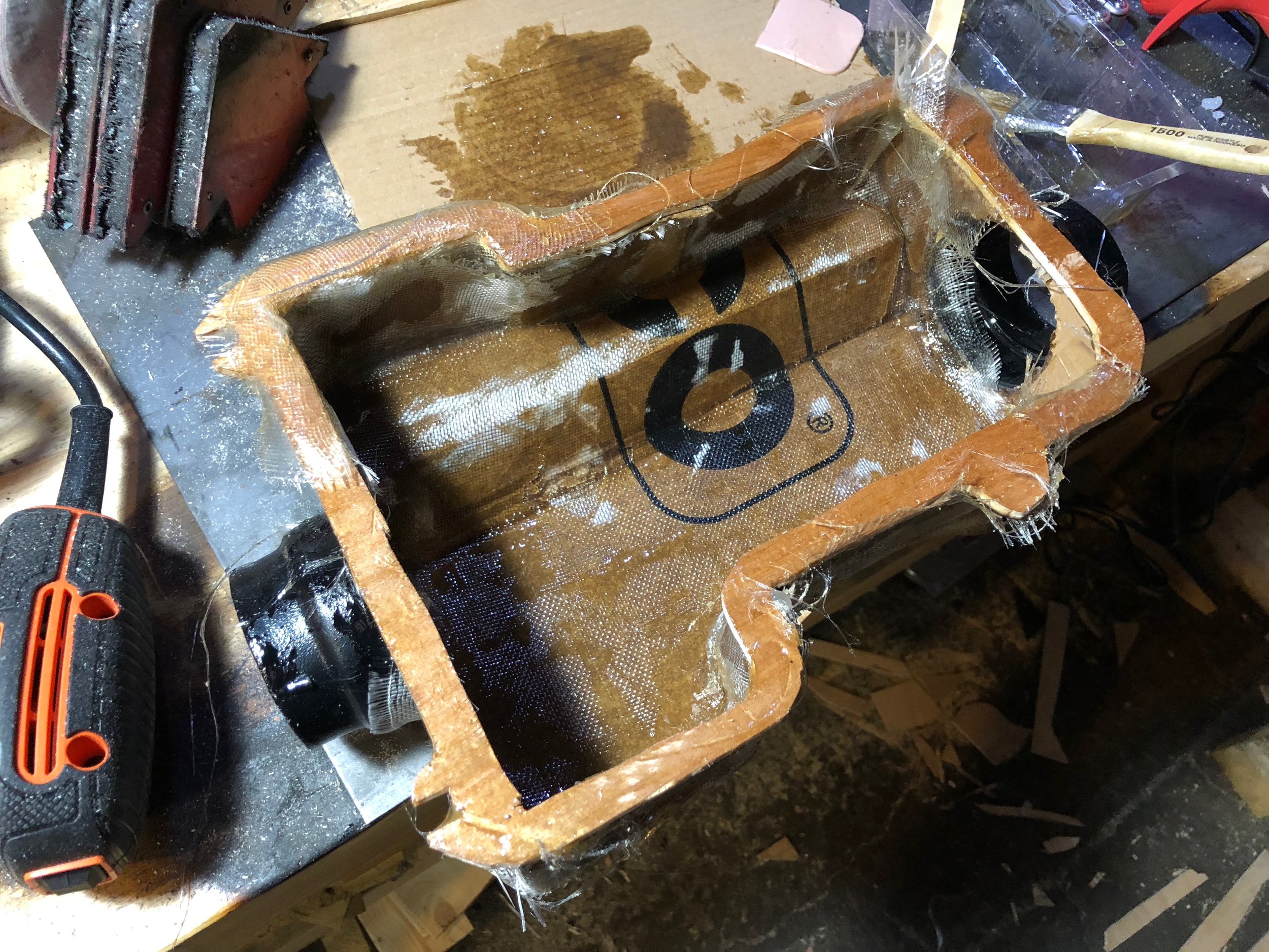
The next step is fiberglassing the box. This is my first glassing project, and for simplicity I used a repair kit meant for body work. This included a piece of fiberglass cloth and a two-part resin. If I had to do it again, I’d use chopped fiberglass mat, as the cloth is difficult to shape around corners and other complex shapes. The end result wasn’t pretty, but is functional, and no one is going to see it anyway once it’s installed. The resin alone hardened the cardboard and sealed the wood enough that I probably didn’t even need the fiberglass other than to cover seams.
Once the resin dried, I poured some water into the box with water and found that it almost perfectly water-tight, save for one corner that dripped a little. I spray painted it black for good measure, although no one would ever see it once the trim was back in place.
For the final installation, I bought a roll 3/16" foam insulation from Home Depot. This has adhesive on one side and easy to bend around corners. I stuck this to the back of my frame to ensure that there was a good seal to the evaporator box. I wound up having to double up a bit to account for my poor fiberglassing job, but it worked just fine.


Sealing the Defrost Return Duct
As mentioned above, there's a duct that runs from the defroster and into the top of the the old air distribution box to provide defroster air to the doors. I'm not using the door vents anymore, so I decided to simply cap this vent. This duct is also 2.5".
I found that the cap to a spray can (brake cleaner or spray paint or something) was just about the right size. I lined the inside with more of the foam insulation to ensure a tight fit. Once capped, I wrapped it with electrical tape to hopefully keep it from slipping off. It was pretty snug already, but I wanted to be sure.
It was a bit of a pain to get it onto the duct with just one hand behind the dash, but I eventually got it. In retrospect, I should have removed the two screws hat hold the duct assembly to the evaporator box to the outside of the car, as this would have made it a lot simpler to install the cap. Oh well.
The cap from a spray can of something, lined with adhesive-backed foam weather stripping material from Home Depot. I added more than this to ensure a good fit, then taped it in place on the defroster duct.
Knee Pad Vents
I wanted square ducts that were easily adjustable on two axes, but actually mountings them and finding something halfway decent looking seemed tricky. In the end I decided to do what some other owners have done (but I can't find a link for anymore), and mount round vents into the knee pads. I went with four 2000-2005 Mitsubishi Eclipse round vents, which I found for under $10 each on eBay. These use the same 2.5” ducting as the original DeLorean setup, although I bought ten feet of new Vintage Air corrugated ducting for my install. The vents also mount flush to the pad, which is a nice bonus. I also bought two 2.5” “Y” adaptors, since I would need to run the duct from the distributor box to the first vent and then to the second vent.
The setup is pretty simple: one vent in each of the driver’s side knee pads, and two vents in the passenger side one. I bought a 2.5” hole saw and drilled the holes from the inside, stopping when I’d cut all the way through the wood or plastic material of the knee pad. I then ran the saw a second time to cut out the foam, which was much easier than my first attempt of trying to cut it out with a knife.
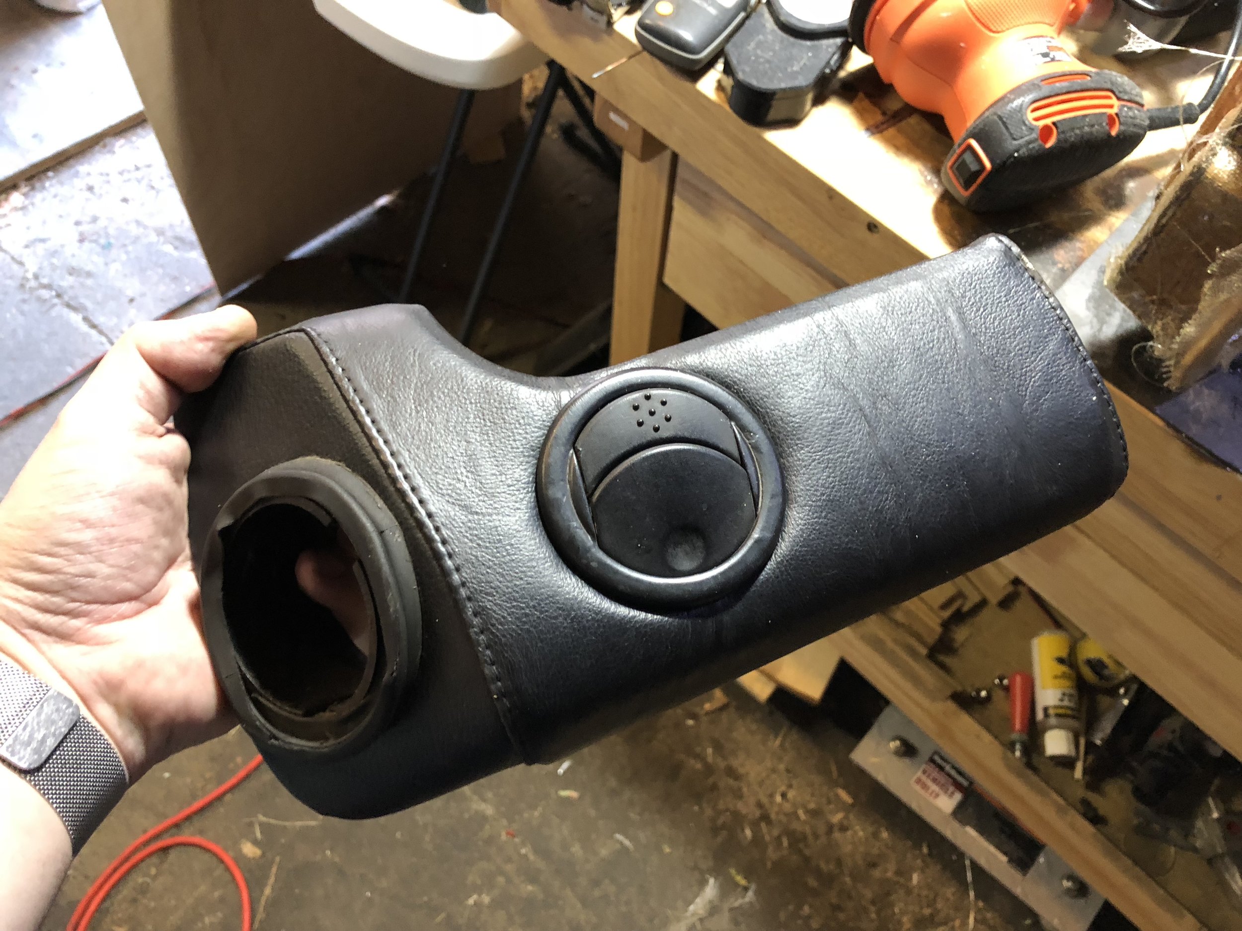
The last cut is into the vinyl covering itself. From the outside I used a knife to cut a plus shape into the vinyl. I didn’t remove the vinyl — I just pushed the vent into the hole, allowing the vinyl to wrap inside. The vent fit snuggly and firmly, and was clearly not going to fall out. Since these vents can only open and close — they cannot angled — I rotated them a bit so that they were more likely to throw air at the person in the seat rather than blowing past them.


Power Outlets
Before I put the knee pads back in the car, I update some power outlets I had put in the driver’s side knee pad. About 15 years ago I’d mounted there cigarette-style power conenctors with dedicated fuses. I removed them and installed a single unit containing one such power outlet and two 2.1A USB ports. This is connected to an extra fuse box behind the driver’s seat. I didn’t need to make any changes to the passenger side, which already had a dual cigarette light and USB port setup. Both of these are mounted on the bottom of the knee pads, so they’re generally out of sight.
Ducting
The 10 feet of 2.5” Vingage Air ducting was straight-forward enough to use. It is a corrugated plastic tube that can be stretched and twisted around corners, and it can be compressed a little if you have to get it through a tight space. I did the passenger knee pad first, since it was a single rigid piece. A short bit of ducting connects the more central vent to a 2.5” “Y” adaptor, while a longer piece runs from the “Y” to the outer vent. I found the ducting is bit tricky to get on. It turned out that if you snip one of the stiff rings first, you can use that to start sliding it onto the duct. The other rings then slip over and hold it in place. It stays quite firmly on its own, although a moderate tug will cause it to pop off. I was willing to take my chances for now and didn’t use any glue or tape or anything to secure it.
Passenger Side Mounting
On the passenger side, I realized I forgot to take into account the glove box when I’d tested the fit. Luckily, this wasn't much of a problem -- I just had to use some longer ducting to the inner vent, and route it down below the back of knee pad a bit so that it cleared the glove box. The ducting still compresses a little against the glove box, but it's flexible enough to handle that and it doesn't affect airflow. I was able to hook up the ducting to the vents, "Y" adaptors and air distribution box before actually finally installing the knee pad itself. Everything went pretty smoothly. I reconnected the wires to the USB/cigarette power module and I was all set.
Driver's Side Mounting
For the driver’s side, I ran new Vintage Air ducting where the old “U” shaped rectangular duct went below the steering column, and secured with the original metal bracket. The ducting is flexible enough that this wasn’t a problem at all.
I had enough duct left over that I was able to attach the outer knee pad's ducting, and then mount the duct onto its bracket. This was pretty easy.
The inner knee pad was another story. I was able to connect the ducting from the air distribution box to the "Y", and from the "Y" to the outer knee pad ducting, but when attached to the inner knee pad the "Y" interfered with access to the nuts needed to secure the knee pad to the bracket. With all my fiddling I wound up dislodging the ducting from the vent.
At this time I found that one of the three usable knew pad studs was loose, so I took the whole pad out and glued the stud back in place with Gorilla Glue. Once it was dry, I laid on my back under the dash, put on the knee pad nuts, and finally re-attached the ducting to the vent, and I was done.


Reinstalling the Center Stack and Center Console
Before I put the knee pads in, I finished setting up the center stack. This is just the reverse of taking it apart, roughly in this order, which is from the longest wires to the shortest.
Connect the radio, including the harness, USB cable, mic, and power antenna,
Attach all the ground wires to bolt on the passenger side of the center stack.
Re-install the four panel illumination bulbs.
Mount the mode switch. It only goes in one way, and is held in place with a screw on the passenger side.
Mount the fan speed switch. This seems like it can go in a couple of ways, but it shuldn’t Matter since you can just rotate the knob before attaching it.
Re-install the headlight switch and hazard switch.
Position the center stack upright on the studs. Due to the depth of my radio, I had to position the radio under the dash, then slightly flex the bottom of the stack to fit over the studs. Make sure to run the three remaining builds through the rectangular opening below the dials.
Tilt the stack forwards and re-attach the vacuum hose cluster to the mode switch. It only goes on one way.
Mount the hot/cold dial, securing it with its nut and washer. The dial only mounts one way., and the short cable means this is one of the last things to install.
Screw the top of the stack into the dash with its two screws.
Re-install the remaining three bulbs into the climate control face plate.
Screw the face plate onto the stack.
Before re-installing the center console, I re-routed one of my ground bus connections a bit. The connection to the harness ground was interfering with the switches, so I moved relocated it further along the bus and wrapped the exposed wire in self-fusing tape.
Moving the ground bus connection back fixed a problem with it interfering with the switch connectors.
After that, the center console goes back in:
Place the center console trim over the console, lining up the holes with the studs.
Make sure the harness wires are inside the "L" shaped brackets, with the holes that sit on the studs.
Reconnect the power window switches, defroster switch, dummy switches, and any other switches (heated seats, in my case). I somehow misplaced one of the
Reconnect the cigarette lighter, if you want. Mine had a broken wire, and I never use it anyway, so I left it disconnected.
Tighten down the nuts at the back of the console, and at the very front at the base of the center stack.
Make sure the bracket in front of the switches is in the correct orientation (ie: lines up with the screw holes in the center console), then tighten down the nuts its mounted on.
Install the sound isolator around the shifter.
Install cup holders, if you have them.
Slide the top of the shifter plate under the climate control front panel, then reconnect the dimmer rheostat and the clock, and finally lay the shifter plate down. You'll probably have to move the shifter to do this.
Push the shifter all the way forwards so that the slip piece will fit under the center console
Screw do shifter plate through the center console and into the bracket.
Install the shifter knob (spring, rod and bottom half, top half, and two screws).
Screw in the rear cubby thing.
Pop the ash tray back in.
That’s it — everything should be back in now.
The mazes that the "L" arm follows for the the headlight switch (left) and hazard switch (right), allowing the switch to lock into two or three positions.
Aside: Headlight and Hazard Switch Operation
A small problem I had was that I had lost the hazard switch spring while diagnosing another issue and thinking the switch was to blame. Luckily, I had an old headlight switch that I was able to scavenge a working spring from. The mechanism for these switches is interesting, and I'm rather surprised it works. An L-shaped metal arm navigates a maze in the side of the switch. When you press the switch in, the arm slides up until it hits a stop, and releasing the button causes the spring to push it out and the arm sticks in the new part of the maze. It feels like it should get stuck or fail, but it seems to work pretty well.
Unfortunately, my hazard switch is sticking. One you press it in, it doesn't pop back out again on its own. It's not a problem with the maze mentioned above, but that it seems the switch just isn't sliding back out properly. You have to pull it out by the button. This wouldn't be a problem if not for the fact that once the faceplate is installed, you can't get a grip on it to pull it out and have to pry it out with something. Since I rarely use the hazard switch, this shouldn't be a huge problem, for now...
Cutting the Double Din Trim
The last bit for the radio is a nice trim piece. I bought a plastic trim piece on Amazon for under $10 specifically for this purpose. The center was exactly the size of the radio; I just had to cut the edges to fit the center console trim.
I used the “score and snap” method to cut the plastic. I laid down a straight edge, then pulled a utility knife along the edge repeatedly. Once it was worn through enough, I simply snapped it off on the edge of my work bench.
I did the top, right and left sides first, as they would be partly covered by the center console trim and would mask my mistakes, which I did make. Luckily they weren’t too bad.
For the bottom edge, I needed a perfect cut.
…to be continued. While it sounds like I did everything right with the trim, I actually ruined two of them because I didn’t cut through hard enough with the utility knife before trying to snap them. Haven’t had time to get back to it while I try to get the car to actually start. I’l update once I’ve got that out of the way.