0
items
$0
Reinstalling the Interior Trim and Electrical Issues
Joe Angell
Before I took the car out on the road, I wanted to put almost everything back in the interior. I was pretty sure I wouldn't need to mess with the wiring again, so this was a good time to do it.
Center Armrest (aka "Center Console")
First, a lesson in why you should follow instructions when reinstalling. I didn't break anything, but I forgot the order for the center armrest enough times that it took me two or three times longer than it should have.
Fit the armrest, making sure that the wires are where they're supposed to be and that the connectors are close to where the switches will go. At least I remembered this part.
Try to fit the mounting holes in the armrest onto the screws, then remember that the heavy cable looms sit on top of those brackets, not under them. The same is true for the throttle cable and my new ground bus.
Tighten down the six nuts with a 10mm socket, making sure the wires aren't getting stuck under them. The copper lug used to secure the ground bus to some wires was slightly in the way, but not insurmountably so, and I was able to fit everything.
Connect the clock wires and re-install the shifter plate light.
Install the shifter plate, slipping it under the climate control plate... and then realizing that I'd installed the bracket that the plate screws into backwards. Since this uses the center two posts of the armrest mount, I had to remove all six nuts that I'd just installed and pull them the loom out of the way so I could flip the bracket around. I was then able to tighten back down those six nuts and screw the shifter plate into position.
Try to install the shifter itself, and remember that the automatic transmission shifter's main shaft has to go on before the shifter plate does due to the detent ring. This meant I had to unscrew the shifter plate, install the post, and screw the plate down again.
Install the screws, plate and trim of the shifter.
Realize I forgot to install the rubber sound deadener around the shifter box. Take the shifter off again, and remove the shifter plate. Insert the deadener, then re-install everything again.
Realize I forgot to put the spring back in when I dismantled the shifter to install the rubber piece. Take the shifter apart again, install the spring, and re-assembly.
Insert the ash tray.
Reconnect the window and defroster switches
I tried to install that bin thing at the back of the armrest, but I could not get it to fit past the wires underneath. I'm not worried about it, since I want to replace this rather annoyingly part of the car with an entirely custom interior some day, and this bit of trim isn't that important to me right now.
The correct orientation of the shifter plate mounting bracket.
The window and defroster connectors ready for their switches.
Another problem is that the passenger window doesn't work. The switch is good (tested by swapping the driver and passenger side switches), but for whatever reason the window won't actually move. This is something I'll worry about when it's a bit warmer out, and after I can actually drive the car.
Turn Signal and Dash Lighting Issues
NOTE: This is from before I installed the double DIN radio, which is a slightly different configuration, but for the most part it’s the same process.
To make sure that I'd hooked up the wires correctly, I turned the key to the Run position and clicked the headlight switch on, and then turned the dial for the dash lighting. This worked fine, and the lights dimmed up and down as expected. The clock was on too, so that was good.
However, the passenger side turn signal indicator on the dash was lit up, which was odd. The driver side signal worked, but flipping on the passenger side just made one click and brightened the light a little, but it never clicked off. Turning off the parking/headlights let the turn signal work properly... except that now the dash lights flashed on and off along with the passenger side turn signal. I found that the hazard lights worked (and flashed the same dash lights), but after that I no longer had any turn signals at all.
I need headlights and turn signals before I can take the car out on the road and test out the EFI system. I was fairly certain that whatever is wrong is behind the climate controls. Of course, the wiring here is a massive pain to get to. The best you can do is remove the center armrest (you know, the thing I just reinstalled), and the radio. The radio was fairly easy for my setup, since it was an aftermarket unit that was designed to be fairly easily removed anyway. I'd long since lost the special removal tool, but a coat hanger works just fine to release the lock.
Getting Access
I managed to get away with just removing the radio and the metal frame that it sits in. The antenna cable pulls straight out, as does the mutlipin connector that provides power and outputs to the speaker wires, and the RCA cables I use to plug in my phone to the radio's aux input. I almost lost the 10 amp fuse on the back of the radio that I forgot was there, and which would have led to a fun time trying to figure out why the radio wasn't working if I hadn't found it.
I also took off the trim plate, which is held on by a single screw behind the multi-mode dial in the center of the plate. This allowed me to remove the headlight and hazard switches so that I could more easily inspect their connectors and wiring. I also popped out the three bulbs along the bottom edge before the plate could be completely removed.
With the radio out, the wiring behind the climate controls is accessible. Here the headlight switch has already been removed and the connector is visible where the radio would be.
Loose Wire
While I was fiddling around behind the console, I lost all power to the headlight circuit. This wound up being a simple lose wire. I had previously installed a common modification in the form of a headlight bypass relay, which keeps the full headlight current from running through the switch (which eventually melts the switch, as it was never designed to handle that much current), as well as a second relay that switches the headlights with the ignition so that I wouldn't forget to turn them off when I got out of the car. The pin for the white wire of the former had pushed out of the relay socket, completely disabling the entire headlight circuit. I was able to bend out the tab on the pin and slide it back into the socket without any problems.
Busted Hazard Switch
Eventually I found out that the hazard light switch had probably failed, and that my test of the hazard lights was the last time it would work (it did require quite a lot of force to trip the switch, and I had to pull it back out to release it). In normal use, the G and LGK wires (the two far left pins on the switch) pass through to the directional lights. It seems that this wasn't working. I actually took apart the switch itself, but nothing seemed obviously wrong. After more tinkering (and blowing the #4 fuse a few times; be careful not to short the connector against the console plate, since it's grounded), I created a jumper from two blade connectors and a short piece of wire, although I had to grind down the blades to fit in the smaller sockets of the connector.
Bypass jumper for the hazard switch, The blade connectors had to be ground down to fit in the narrower pins of the socket.
Turn Signal Circuit Tests
This gave me back my turn signals. Somewhere along the line, though, I lost the dash lights entirely, in that they wouldn't turn on at all no matter what position the headlight switch was in. They did still blink with the right turn signal, so there were still have two problems to solve.
I decided to rule out any other shorts in the turn signal wiring, as suggested by others on DMCTalk. I removed the front right turn signal and checked to make sure the filament wasn't damaged, as apparently one of the filaments in the bulb can break and short the other, causing the turn signal to remain on. I also disconnected the marker light, which I had modified into a turn signal. I did the same for the rear right, disconnecting the entire tail light board. I also annoyingly pulled the connector off the wire to the rear right marker light, and had to spend 10 minutes reaching a few inches into the taillight space trying to fit a new connector and crimping it on, but I finally got it. None of this mattered -- the turn signals still flashed the dash lights, and the dash lights wouldn't come on with the headlight switch anymore.
Binnacle and Instrument Cluster Tests
One suggestion from DMCTalk was to check the connectors on the back of the instrument cluster. The pin for the dash lights and the turn signals are right next to each other, and if the connector was a bit misaligned it could cause this kind of problem. It was unlikely, but worth a shot.
There are six nuts that require a 7mm (or 9/32) socket to remove to take off the binnacle. To get to them, you'll have to remove both driver's side knee pads. Each has four nuts that require a 10mm wrench to remove, and you'll have to pull out the accordion-like duct on the on the left side knee pad first to get access to some of the nuts. The plastic rectangular ducting from the center of the car to the door also has to come out, but it's only held on by a simple metal bracket, which itself is secured by two easily-removed Philips screws. With those out of the way, you can get all six of the small nuts out.
Before lifting the binnacle, you'll want to disconnect the speedo cable at the angle drive, or else you won't have enough slack to lift it very far. Once free, you can raise it high enough to disconnect the speedo cable from the binnacle (push the button at the bottom of the connector) and unplug the cables. I didn't actually need to do that -- I just wanted to see how the connections were. Everything looked fine and tight. The problem looked like it was elsewhere.
Removing the Center Console (again)
So we're back to the center console. I reversed the instructions above to remove the console, and started tracing the wires.
Tail Lights
At one point I disconnected the black bulkhead connector in the engine bay, and suddenly the turn signals behaved normally. This meant the problem was somewhere int he tail light harness.
Years ago, I'd made a few modes to the lighting circuit. I'd install backup sensors that tapped into the reverse lights and ground; I'd modded the marker lights into turn signals; and I'd installed a high-center stop light that is connected to the brake light and ground. All of these are tapped near the passenger side tail light connector.
Apparently, I hooked up the market light warning wrong, and effectively plugged the tail lights into the right turn signal. When the headlight switch is depressed, it turns on the tail light sand dash lights. By plugging the turn signals into the tail lights, I was also powering the dash lights.
I unplugged the marker lights and returned them to factory. The turn signal mod doesn't work anymore anyway; I had previously installed LEDs, and the mod relies on switching the marker lights from 12v/ground and ground/12v. This works fine with incandescents, but LEDs are polarized, and will not light up if plugged in backwards. At some point I'll use some DigiSpark microcontrollers I have lying around to restore this functionality, but for now I'm happy to just have working turn signals again.
Marker Lights
It turns out that I didn't hook the marker lights up correctly, again. I finally realized that when I'd taken everything apart four years ago, I had pushed the wires mostly of the way into the body to keep them from getting snagged on anything. When I pulled them out, I found the positive and ground wires. I somehow thought that there was only one wire on each side, and the other wire ran through the body somehow, but no, both of them were there. Of course, I mangled the driver's side socket thinking the LED had failed and had to replace it before I figured this out. To get to the wires, I had to remove the rear fascia again. I've done this enough that it's starting to be easy.
I reconnected the striped wires to their matching marker light wires using spade connectors. I also used spade connectors for the ground wires, which had long since been stowed away as part of the turn signal mod. Now everything was back to factory, and the marker lights worked correctly.
Door Light Switches
I took this time to replace the switches for the door lights. I'd previously removed the original lights and replaced them with LEDs, and swapped the switches out with magnetic ones. The switches were normally closed instead of normally open, which meant the lights would be on only when the doors were closed. I fixed this with a transistor to flip the behavior of the lights, but the transistor needs to be powered to work (not much power, but still).
The circuit on the passenger side door stopped working, so I bought a new set of magnetic switches, this time with three wires (common, normally open and normally closed). I connected it the stock wiring up to the normally closed part of the switch, and everything works as expected. I replaced the driver's side switch while I was at it. The only "problem" is that the switches are white, but a bit of black spray paint fixed that.
That left the issue of the center red light on the passenger door. A component failed in the LED assembly I was using, so I simply ordered another one and popped it in. My original LEDs were from a kit sold by DeLorean.com, and a replacement was only $4 plus shipping.
Passenger Door Issues
The passenger side power window refused to operate at all. I tried swapping the window switches, and applying power directly to the pins in the connector behind the passenger seat, but it was no good. I had to take the door apart and check the motor.
Taking the door apart is a bit of a pain, and even more so with the window up. You need to pop out the upper trim, but that's most easily done with the window down from the outside. I used a 90 degree bend pick that I could slide between the window and the trim to pop the trees. It wound up accidentally popping them out of the trim instead of the door body, but they were easily re-inserted once they were removed.
Unfortunately, the motor is in the lower part of the door, so the lower trim also had to come out. This mostly involves taking out the plastic tray under the release handle, then removing a series of Philips screws that hold the trim in place. The hard part is the door handle itself. I had always been told that the way you do this is by pulling the trim away from the front and back of the door while inserting a long screwdriver all the way to the handle to remove the screws. Some Googling found this page (which seems to be a broken link now), which showed a much simpler alternative method of removing the handle via two bolts accessed through the space around the door handle with an 10mm socket. Annoyingly, one of the bolts simply spun when I tried to remove it, so I had to resort to doing it the original (and much more difficult) way.
With the door apart, I found that someone had striped the blind nut that was welded to the handle bracket, and had just put a loose nut in its place. I removed this nut and used an M6 Helicoil-style rethread kit to fix it, as I really wanted to use this new method to remove the door panel in the future. To get access for the Helicoil tap, I had to remove the door handle lever and lock switch assembly, which involved disconnecting two rods (they just have a simple clip and then pop out of their greased pivots) and removing a few more screws, but this was straight forward. It wound up being harder to get a wrench on that free-spinning nut to rethread it. The Helicoil was actually longer than the hole, and I wasn't able to break off the tang, so I just left it there. This causes the free-hanging end of spring-like Helicoil stretches out when the bolt is screwed down, but it doesn't affect anything. Normally I prefer TimeSerts, which I've used on the engine in the past and wouldn't have this problem, but the $15 Helicoil-style kit for this simple, non-critical task was much more cost effective than a $70 TimeSert kit for one job, and seems to do the trick just fine here.
I also had to do a bit of work on the pull handle itself. I replaced the two Philips screws with M6 bolts. The screw heads were mangled and stripped, and the holes in the handle were cross threaded and worn. I ran an M6 tap down the holes to rethread them, and then inserted new M6 bolts. They were a little long (you can feel them pushing against the covering inside the handle), but they work just fine.
The upper and lower door panels removed. The power window motor is on the front bottom of the door (lower left of the picture).
After removing the door lock and handle controls, the pull handle bracket was clearly visible for tapping.
The door with the lock and handle mechanisms out of the way.
The newly-installed Helicoil, visible on the far side of the bracket on the right of the image.
The bracket re-installed on the handle and fit in the lower trim, ready to be mounted back in the door.
With the lower panel out of the way, I could finally inspect the motor. It turns out that one of the two wires had come unplugged from the motor. I have no idea how this happened, but it was simple to reconnect them. A quick test showed the window as once again working perfectly. With that done, I re-assembled the bottom of the door.
The wire on the window motor that somehow got unplugged, requiring the disassembly of the entire door to get to it.
I also took this opportunity to replace the "fuzzy caterpillar", which is the felt between the passenger window and the door body that keeps the window from getting scratched. Mine had come loose on one end and kept getting caught in the window. It was only $15 for new felt from DeLorean, so I removed the nine Philips screws holding the black retainer in place and easily pulled U-shapped piece with the felt off. I used 3M black weatherstripping adhesive to secure the new felt, then re-assembled the retainer. Of course, I somehow managed to misplace all of the screws that held the retainer to the door, and had to run to Home Depot to grab some roughly compatible machine screws to finish the job.
Door Launchers Firing when Turning the Key
Next, the door launchers, which I'd installed long ago. Turning the key to Accessory caused the launchers to fire, and to hold position. Besides the obvious problem of the doors opening (well, as best they could; they tended to get stuck on the very tight weather stripping), a bigger problem was that they stayed powered until the key was turned off. The actuators weren't designed to be held that long, and would not release the door handles once power was cut. Manually moving the rods by hand fixed this temporarily, but required that the upper door trim be removed for access.
I finally figured out that if I turn the key to the first position, pause for a couple seconds, and then turn it to the second position, it's fine. But if I quickly move past the first position to the second position, the actuators trigger.
The DeLorean Parts Northwest door launchers use a module in the relay compartment. I quickly found that the small two pin connector with black and red wires had come unplugged. My theory is that without these wires, a microcontroller input was left floating, and turning the key quickly would cause it to think that the button had been pushed to open the doors. Plugging that wire back in immediately fixed the problem.
...or so I thought. A few weeks later I found the problem had returned. Since I had nothing controlling that module anymore, I just disconnected it to deal with it another day, probably when I build my own door launcher controller. Later I removed it entirely so that I could clean up the relay compartment a bit more and more easily put the wooden cover over it.
Parcel Shelf Backing
I routed the EFI wiring and the original DMC harness above the top parcel shelf bracket. I had to redo some of the self-fusing tape I’d wrapped the EFI harness in so that it would reach, and lengthen the purple (fuel relay) wire and the slate/white (tach wire, which it turns out I forgot to connect at all until earlier that day) so that it would reach cleanly. The orange fuel injector power wires and the green/orange coil power wires wouldn’t reach, so I left them resting on the shelf to be covered by the carpet.
I also relocated the LC2 electronics to the driver’s side pontoon. This made it easier to get to since it was under the electronics tray anymore, and it resolved some wire runs and cleaned up the tray.
The parcel shelf backing is a bit of a pain, since you have to rest it its wire loops on the hooks before tilting it up. I’m pretty sure I missed the loops, but it holds just as well. After that, it’s just a matter of screwing in the cargo net hooks. Remember that there are two longer hooks and two shorter hooks. The longer ones go on the ends, and the shorter ones in the middle.
The relay covers are just the original wood, and drop into place, luckily clearing the newly-installed EFI electronics. The carpet then simply lays over the top.
Before covering everything up, I sealed a few holes, such as those for the MAP vacuum line and the O2 sensor, with Dynamat, effectively using it as a plug in place of a grommet, since I was never quite able to find grommets of the right size. I also had to cut and re-solder one wire I ran to the front of the car due to accidentally running it through the cargo net, but that wasn't much a of a problem.
The relay compartment, ready to be covered.
The harnesses running along the top of the back wall, minus the fuel injector and coil power wires, which run along the bottom.
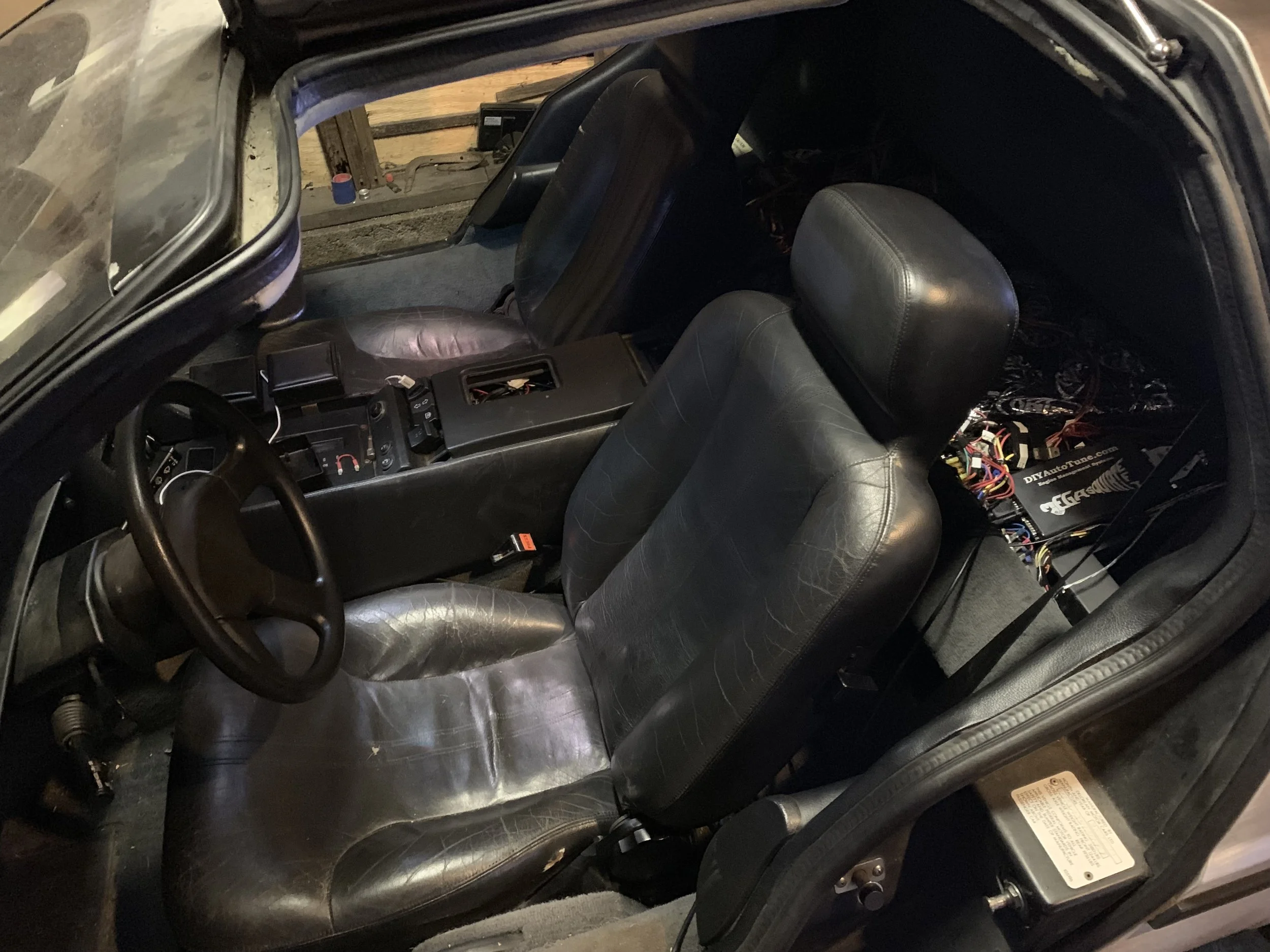
The ECU compartment behind the driver’s set, mostly neatened up.
Passenger Seat
I’d never removed the driver’s seat, but taking out the passenger seat made it much easier to work in the relay compartment. Now it was time to put it back in.
The rails can’t be simply placed directly on the floor, as they sit too tight against the carpet and you can’t slide the seat forwards and backwards. I’m not sure if there were spacers originally, but I needed to add some. In my case, three washers on each of the four studs fixed the problem. To hold them in place I used some leftover black A/C caulk strip, being careful to avoid the threads on the studs.
Before trying to put the seat in the car, make sure that the rails are both in the same position relative to the seat (say, all the way back). When not in the car, the rails can move independently. I of course didn’t notice this until I had the the first two studs in place and secured with their nylock nuts. I had to use vice grips to grab the rail and drag it back while pulling the hands up. I finally got it.
Of course, I couldn’t actually put nuts on the inner studs — both were stripped clean of threads. At least two studs were secure….
Engine Cover and Louvers
While not the inside of the car, I still consider the engine cover and louvers to be trim, more or less. The engine cover itself wasn’t too bad to install. I placed it over the engine bay, then rotated the hinged studs down through the cover, and then tilted it upwards, installing nylock nuts onto the studs while using my head to keep the cover open. Next the engine cover stay is bolted to the firewall, again while holding the cover itself up with my head.
The louvers were more of a challenge. I misplaced the passenger side stud assembly, so I used two stainless steel M8 bolts in its place. Luckily there was just enough clearance for the bolt heads. After one of the bolts was through, I put the stud assembly through on the other side, and finally the last bolt into the passenger side. I then raised the cover, attached nylocks to the drivers’s side studs, and then attached nuts to the passenger side bolts.
At this point I realized this would have been a lot easier if I’d attached the struts first, since they would have held up the weight of the louver. I dropped it on the cover a number of times while trying to get it aligned and mounted.
I also had an alignment problem, where the louvers were too close to the driver’s side when closed. The solution was to loosen the passenger side bolts, then push the louver back as far as I could before tightening the nuts again. That fixed the alignment and got it back to good.
The last steps were to re-connect the wires for my third brake light and re-install the cover under the T panel that protects the ends of the torsion bars. Both went smoothly.
Aside: Moving the Fuel Pressure Gauge
I didn't realize it when I set it up, but the fuel pressure gauge is covered by the ducting for the air intake, which makes it difficult (but not impossible) to read. I thought it would be a good idea to move it to the bulkhead for easier access.
I wanted to put it where the ballast resistor was, which meant I had to remove the resistor. I couldn't get a wrench on the bottom bolt, so I wound up bending the bracket and grinding it off from the back, then bending it back. That worked just fine.
I had a spare "T", some fuel hose, two fuel hose ends, and a cap. I installed all of these, then turned on the fuel pump... and watched it spray fuel all over the engine bay.
For whatever reason, I couldn't get the connectors on the "T" tight enough, and they just leaked fuel all over. The cap at the end of the fuel gauge adaptor was just completely wrong, and wasn't designed to ease this kind of connection, so it just leaked fuel down the firewall. This whole thing was a complete failure. After some more fiddling, I just returned everything to how it was before.
Some searching on JEGS finally turned up a solution: male 1/8" NPT to AN-6 hose ends (JEGS part 555-103200), and a female to female 1/8" NPT 90 degree adaptor (JEGS part 361-991601). I simply unscrewed the gauge and re-installed it on the the 90 degree adaptor. For the hose, I just removed the AN-6 ends from the one I'd made before and installed the 1/8" NPT ends. The assembled hose was screwed into both the 90 degree adaptor and the "T" that I had previously installed the gauge on. The system didn't leak at all once pressurized -- I call this a success.
Mounting the gauge was a little inelegant, but it's sufficient: I used zip ties where the blast resistor was. I couldn't get to one of the nuts on the resistor, so I wound up bending the steel plate and cutting it off from the back, then bending it back to its original location. At some point I might drill through the plate and install a rivnut into the fiberglass, but likely only if it rattles around too much.
Failed attempt at relocating the fuel pressure gauge, and all the leaks that occurred.
Alternate setup that works, with male 1/8" NPT to AN-6 hose connectors on both ends, and a 1/8" NPT female to female 90 degree adaptor at the gauge.