Building an IKEA Lack Enclosure for the Ender 3 Pro
Joe Angell
Update: March 2023
I’ve updated the article with more current pricing and links to many of the parts used to build this project. As an Amazon Associate I earn from qualifying purchases (learn more here), so if you want to support me, that’s a good way to do it. The prices shown are approximate and current as of March 2023; they’re just there to give you a rough idea of how much something like this might cost.
Nearly four years later, this enclosure is still set up and in use, although a lot of my printing has moved to PETG with an AnkerMake M5. I still do use it when I need to print extra parts, though, or have the need to print in ABS and need to get rid of the fumes.
November 2019
I recently got an Ender 3 Pro 3D printer. It works great, and I’ve been doing a lot of little projects and prototypes with it. Since I plan on working in an automotive environment, I’m using ABS to ensure that parts don’t melt in the engine compartment or from the hot sun in the cabin.
To print with ABS, you really need an enclosure. This traps the heat in, reducing the chance of warping. For a while, I used a photo tent, which was cheap and worked pretty well. However, it was hard to look at the print while it was printing, the fumes would get annoying, and the VOCs released by ABS aren’t good to breathe — and the photo tent had no provision for venting. Something more robust was needed.
Design
I modeled my design on a Prusa enclosure. This features a series of 3D-printed parts that take around 40 hours to print. These parts mount at the corners to hold the plexiglass panels in place and include pieces for double-hinged doors, a spool holder, a shaft to run the filament from the spool through the top of the table, and a few other odds and ends (power supply mount, cable clips) that I didn’t use.
Besides the 3D printed parts, this requires a few more pieces:
Two (2) IKEA Lack side tables. These were $10 each from IKEA, back when I built this in late 2019, but as of early 2023, they’re about $15-$17 each. If you don’t have an IKEA nearby, you can get them online from other vendors in white (two-pack), black-brown (two-pack), and oak (I couldn’t find a link for that one), although you will pay more than you would just by going to an actual IKEA.
The plexiglass is mounted between the legs of one table, which is then placed on top of the other table. I later used a third to raise the printer up higher and provide storage underneath.Plexiglass sheets, such as these. I was able to buy a complete set of tinted 440mm x 440 mm and 440 mm x 220 mm pieces specifically for this for about $65 on Amazon. You can probably get them cheaper if you cut them yourself, but this was very convenient.
Screws. I just used some sheetrock screws I had lying around.
For the most part, the design worked quite well. I ran into a few issues, though.
Plexiglas Size: The plexiglass sheets were slightly too tall (or the legs too short), which made it impossible to properly seat the corners. It wasn’t a big deal, but it affected my ability to seal the enclosure and keep the VOCs in. I worked around this by printing a series of 1mm and 2mm shims that I could insert to between the bottom feet and the legs to get the height right. Spacers STL
Printer Height: A bigger problem is that the Ender 3 Pro is slightly taller than the Prusa. I fixed this by printing new feet with 20mm risers. This introduced a 20mm gap between the glass and the bottom table top, which I filled with 1”x3” wood strips painted black. Tall Feet STL
Printer Depth: The printer barely fits in the enclosure front-to-back, with the bed coming very close to hitting the front and back as it moves. Once I had the final position figured out, I put two screws down in front of the printer to act as stops so that I could align it again easily in the future.
Spool Holder Width: The printed spool holder was designed for wider spools. I loaded the STL file into modo and reduced the width of the base to properly hold the smaller $20 spools I had been getting from Amazon. Modified STL I later bought an inexpensive acrylic spool holder that was a bit more robust and turned more smoothly.
I also wanted to know how hot the enclosure actually gets. I bought a refrigerator thermometer with a temperature probe to track this. Most of the small thermometers I found were meant for grow rooms and cycled between temperature and humidity, which is not what I wanted. The one I found was around $10, and the probe let me mount the display outside the enclosure.
I originally considered adding a heater, but some Googling and my own testing showed that this was not necessary. The enclosure gets up to around 108 F purely through waste heat from the bed and nozzle.
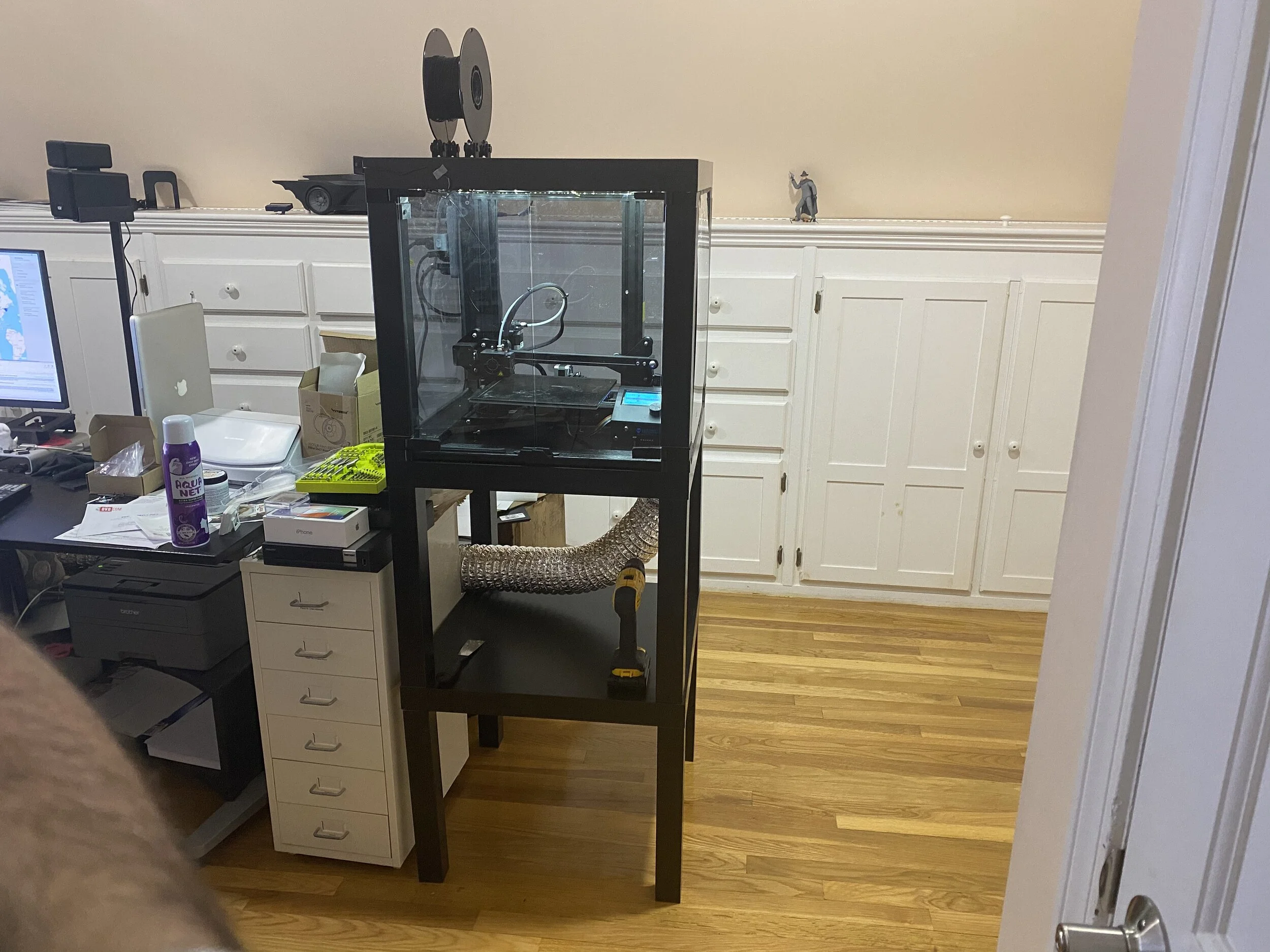
The modified spool holder on top of the printer.
A digital thermometer shows the current enclosure temperature. It gets up to around 108 F when printing — no extra heater is needed.
Sealing
I wanted to get rid of the VOCs, which first meant keeping them in the box. This was pretty simple: I bought some adhesive-backed rubber automotive seal, similar to this, from the hardware store. I ran it along the legs and top of the table just behind where the glass would slide into the mounts, then inserted the glass. The glass presses against the strips, making for a reasonably tight seal.
The doors aren’t sealed. I’ve run the printer this way for over a month and don’t even notice the VOCs anymore, as the majority are sucked out through the vent. The extra sealing isn’t necessary, and in fact, it’s arguably useful to leave it unsealed to act as an intake to keep air moving toward the vent.
Adhesive-backed weather stripping used to seal the sides of the enclosure.
Wooden strips used to fill in the gaps between the bottom of the glass and the bottom table top after adding the risers to the legs.
Ventilation
Next, I had to get the VOCs out of the box, and out of my room. For this, I bought a 4” 100 CFM exhaust fan for about $28. 100 CFM isn’t terribly strong, but it works just fine — it’s strong enough to pull the fumes out without removing all the heat from the enclosure.
I bought a $14 4” duct mount, and cut a hole in the bottom of the enclosure, then screwed the mount over that. I positioned it near the power supply so that I could try to keep air flowing over it, but later moved the power supply out of the case entirely — the stock cabling was just long enough to do that.
I ran 4” dryer duct between the enclosure and the fan, and then from the fan to the window. On the window side, I bought a shelf from the hardware store, then cut a hole in it and mounted a louvered cover on the outside, and attached the ducting to the inside. I couldn’t actually fit the shelf into the window opening in one piece, so I cut it in half, put the two pieces in, and screwed them into a third piece of wood. Before installing it, I used some more adhesive-backed weather stripping to keep drafts out.
I did try to use a hinged backdraft blocker to keep the cold air out, but it didn’t work. I got one that had gravity-assisted closing and one that used weak springs. It turns out 100 CFM across 4” is not strong enough to open either of those. The louvered piece outside should be enough to keep most air and weather out, so I just it alone. I did consider a stronger fan, but the price jumps quickly, and I was trying to keep this cheap.
The duct routing in my office.
The duct running from the bottom of the enclosure.
The exhaust fan in the middle of the ducting.
The duct going out the window.
Lighting
I bought a simple LED light strip and spiraled it around the top of the enclosure. I snuck the power wire out the top of the enclosure and taped the power supply to the back of the enclosures. The strip is dimmable, and I mounted the included dimmer on the back of the enclosure, although I just leave it at full brightness.
LED lighting spiraling around the top of the enclosure to light up the print.
The dimmer crudely attached to the back of the enclosure.
Power
The printer, fan, and lights are all plugged into a power strip attached to the side of the enclosure. I can turn on the strip to turn on all three at once. I also put a switched outlet adaptor on the fan so that I could either run it all the time or only run it at the end of the print.
The power supply was moved out of the enclosure to keep it out of the high-temperature printer environment. The stock wiring just barely reached. It’s simply secured with a zip tie, which seems to be fine. Moving it outside should increase the power supply’s life, but likely wasn’t strictly necessary. The steppers are still in the enclosure, but there’s not much I can do about that.
Printer, fan and light power all plugged into a single power strip. Toggling the switch toggles all three at once. The fan has a separate switch on it so that it can be separately turned off if desired.
The power supply (silver, below the white power strip) mounted outside of the enclosure with a zip tie. The LED dimmer can also be seen above the power strip.
Results
I’ve done many prints since building this enclosure, and the VOCs are basically nonexistent in my office. The majority of my prints now come out with no warping at all. I sometimes have to apply more Aqua Net Extra Super Hold hairspray to keep the prints stuck to the bed, and sometimes I’ll have a feed error that results in strings of plastic everywhere, but these are rare, and the ABS prints themselves are good and solid. Overall, I’m pretty happy.