Rear Shock Tower Reinforcement
Joe Angell
About 3400 miles after replacing my rear shocks with KW coil-overs, I started getting some squeaking from the back of the car. I actually noticed this on the way back from DCS, but I thought it was just an engine cover lift piston squeaking when I hit bumps.
I eventually became persistent enough that I spent some time tracking it down. This didn’t take long — bouncing the rear right fender made it squeak quite reliably.
As an Amazon Associate, I earn from qualifying purchases (learn more here), so if you want to support me, that’s a good way to do it.
Checking the Bushings
I was able to localize the sound to the top of the rear right shock, so I started by checking the shock bushings. They didn’t seem as compressed as I expected them to be, which was odd, so I torqued the nut down a bit more. Unfortunately, that didn’t fix the squeaking. I tried torquing it down more, but it still squeaked.
Comparing the Shock Towers
I decided to just compare how squeezed the driver’s and passenger side bushings were under torque, and found something rather unexpected.
On the driver’s side, the top of the tower has a bowl-shaped. I believe this creates an arch that distributes the load from the center of the tower to the reinforced edges, reducing the chance of failure and allowing for the use of thinner materials (the DeLorean frame is made from rather thin layers of 16 gauge steel).
The passenger side was bowed up. That seemed bad.
I pulled out the passenger side coil-over and found the top of the shock tower to be fairly rusty. I broke away the pieces that I could and used a Dremel to remove some other bits.
The failed shock tower. That dome should be a bowl.
Fixing the Shock Tower
At this point, I was running through the options for how to fix this. Ideally, I’d cut off the top and weld in some thicker steel. I didn’t think I could reproduce the arch, but simply welding in a thicker piece of steel should solve the problem.
The problem is that there isn’t any access. I’d have to pull the body off the frame to do this, and I really didn’t want to spend the time unbolting them from each other and disconnecting everything that ran through the firewalls.
The extreme option is to replace the entire frame, but my frame isn’t that bad, and if I’m going to replace the frame, I’d get a stainless one. But I’m not sure anyone is making stainless frames at this point, and I don’t want to do any conversions at this time, so that’s out too.
I decided to go with the simple fix: try to crush down the bowed-up top of the tower, then bolt a steel plate underneath. Only the center was rusted — the edges were still in good shape. A thicker piece of steel should distribute the force to the edges.
Getting the Plate
I was able to order a couple pieces of 5” x 5” steel plate in 1/8” and 1/4” thicknesses. It looked like 1/8” would be plenty thick for this, and certainly thicker than the stock frame. 5” x 5” is the perfect size to fit inside the shock tower — I didn’t even need to cut anything.

The 1/4” and 1/8” thick 5” x 5” steel plates.
Attempting to Crush the Bowed-Up Part
The first thing I did is mark the center of the plate and drill a hole in it. I then placed it under the shock tower and used a nut, a bolt, and a stack of washers to create a kind of press. I used a wrench to try to crush it down, but it didn’t seem to do much — in fact, it seemed to just slightly bend the 1/8” steel plate more than it did anything to the tower itself.
This meant there was a gap between my new steel plate and the top of the tower, and I was afraid that would prove to be a weakness. I decided to resolve this by welding a few thick washers to the top of the plate, effectively filling the gap.
Drilling for Bolts
This seemed to work, so the next step was to drill holes for the bolts. I had considered welding it in place, but there is very limited access. Also, most of the weight would be taken by the center of the plate where the bushings clamp it to the tower, so anything else is mostly to just hold the plate in place and keep it from rattling around.
My plan was to drill a hole at each corner for M6 bolts. I was limited by where the spring collar sat, meaning I couldn’t put the bolts in too close to the center.
This seemed like a good idea, and the outermost holes went in easily enough. The problem was the inner corners. Those are tucked under the frame, from above the fiberglass body is in the way. There wasn’t really a good way to drill those holes.
In the end, I decided to just go with holes only in the two outer corners. Combined with the shock going through the center, this gives three points of contact that should keep it stable.
Drilling the holes in the plate.
Failure
This was a mess. First, I failed to drill the holes in the right place multiple times, and wound up having three holes on one side of the plate and two on the other. It’s ametureisly bad.
The second thing I forgot to consider was how much of the shock stem was actually threaded. When I tried to install it, there was no room for the nut. I should have noticed this much, much earlier.
The stem won’t clear the plate and washers once the bushing is installed.
The Good Version
It was clear that I needed to do something about the gap that would both reinforce that location while still providing enough room for the shock stem to properly stick out of the top.
I eventually hit on the idea of using my press and a pair of 3D-printed dies to press an inverted bowl shape into the steel plate. I printed the dies with 100% infill in PLA. Whie the inverted bowl shape is the opposite of what was originally there — a bowl that would distribute the load to the edges — the much thicker steel I was using should mean that it should still be stronger than the original. Not that I’ve done any kind of analysis on this or anything, but it seems like it will work.
The cross section of the dies used to press the plate.
Pressing the plate was mostly successful. I designed the dies to take into account the thickness of the metal, so if everything went perfectly correct the plate would be exactly formed to the shape of the die. However, the positive die was itself crushed a bit by the pressure, resulting in the plate being not quite as deformed as it should be.
Pressing the plate with the dies.
I resolved this by 3D-printing a new positive die that was exaggerated enough that the pressure damage should bring it back to the desired final shape, more or less.
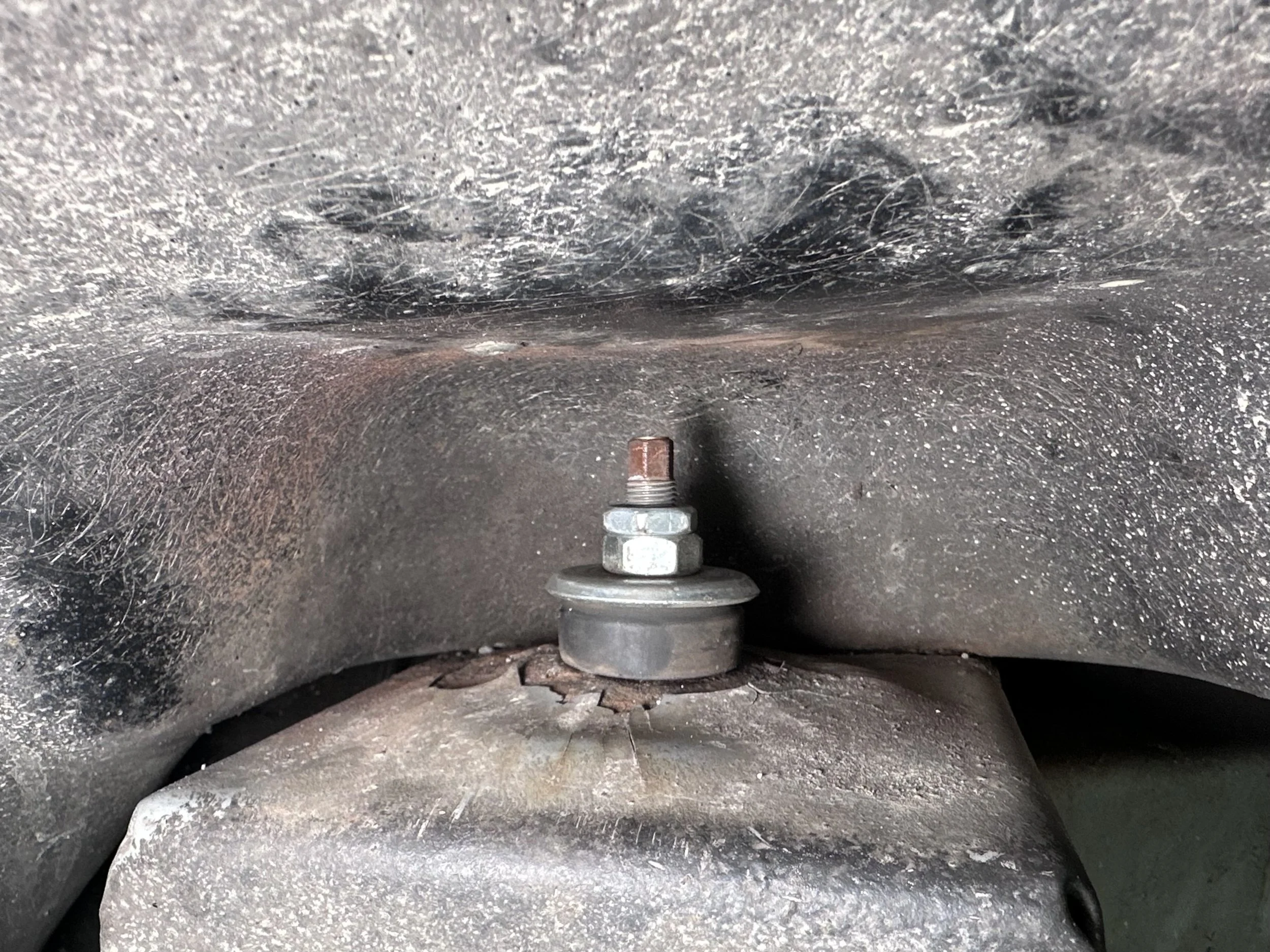
While I waited for this to print, I decided to try crushing down the raised top of the shock tower again. I drilled a hole in the center of the thicker 1/4” steel plate, bolted it in place, and used my impact gun to try to crush it down. This time it worked — I got the bowed-up part of the tower to sit flush.
Using an impact gun, a steel plate, a bolt and some washers to flatten the top of the shock tower.
This left a relatively small gap, which was easily filled by the plate I’d already pressed with the original dies. The bushing fit in there pretty well, so I didn’t need to use my newly printed die.
The depression created with the plastic dies is all I needed after flattening the top of the shock tower.
I needed to mark the bolt holes in the plate before I could drill, and I wanted to do it correctly this time. The problem I had before was that I couldn’t fit a marker between the body and the frame.
In the end, I made a “marker” out of a Q-tip and some black paint. The Q-tip was easy to bend and fit into the holes I made in the tower, and the black paint clearly marked where the holes should be. Once they were drilled out, they lined up perfectly.
Using a Q-tip dipped in paint to mark the holes on the plate through the top of the shock tower.
I painted both the new steel plate and the shock tower with multiple coats of POR-15, bolted them together, and installed the shock.
Final Result
And it worked! The squeaking is gone, the tower is reinforced, and the car rides just fine. This may have slightly affected the suspension geometry, but I don’t think it’s significant enough to matter. Not that I know anything about suspension engineering, but I’m not exactly pushing this car to its limits either. I’m sure it will be fine.