DeLorean UK's Big Brakes
Joe Angell
I’ve had a persistent issue with the brakes in my DeLorean. The first press of the pedal would go to the floor pretty easily, but the second was firm. This would reset every minute or so. I just got used to double-pumping the brakes.
My wife wasn’t happy with the possible safety issues and got me the Big Brakes system from DeLorean UK. This performance brake system significantly improves the DeLorean’s braking. Martin at DMC UK was a big help with all my questions, too.
This was written a few months after installation, so it may be a bit sparse in a few places. Be sure to check the instructions that came with the brakes, as they include important notes.
Raising the Car
All four wheels need to be off the ground for this job. I normally put pallets under the wheels, but this time I placed two under the engine subframe and one under the center of the front frame extension. My pallets are wide enough that this was plenty of support. Four jack stands should work just as well.
Before raising the car, loosen all the lug nuts. Once the car is up, you can take the nuts off the rest of the way and remove all four wheels.
Removing the Old Brake System
Removing the existing brake system is fairly straight-forward. First, all four wheels of the car have to come off the ground. After loosening the lug nuts, I jacked up the front first, placing my pallets under the jack points behind the front wheels. I then raised the back of the car and placed pallets under the engine subframe. After that, the lug nuts and wheels were completely removed.
Front Brakes
The front brakes rotors are mounted to the wheel hub. This means the hub has to come off. The front hub likes to disassemble itself, so you should buy spares just in case. One of mine came apart, while the other remained intact.
To get the hub off, you use two large wrenches, one on the front and one on the back. 1 1/4” seems to work. On the driver’s side, the back nut also holds the angle drive.
With the wheel off, the hub, caliper and angle drive dust cap covering the hub nut are visible.
A closer view of the hub without the dust cap The angle drive end can be seen sticking out of the large center nut after the dust cap is removed..
Using a 1 1/4” wrench to remove the center nut.
An open end wrench is used to remove the nut on the back, and to pull off the angle drive with it.
Next the brake line to the caliper has to come off. You’ll want something to catch the brake fluid that drains out of the lines and calipers. You will not be keeping the fluid, no matter how new it is. You need to always use new fluid.
You really only need to disconnect the flex line from the hard line, but I disconnected the hard line as well. Use flare wrenches to avoid rounding the nuts, in this case 11mm wrenches. You’ll also want to remove the flex line itself, since the big brake kit comes with new ones. I used one 11mm flare wrench and a 13mm open end wrench for that.
An 11mm flare wrench used to remove the brake line from the caliper
Using a 13mm wrench to remove the other end of the flex line from the hard line to the brake reservoir.
The 11mm and 13mm flare wrenches used to remove the brake caliper hardline, which isn’t strictly required for this.
Make sure you have something to catch the brake fluid when you disconnect the lines.
I removed the brake pads next. This is necessary to later remove the caliper from the wheel, although you can wait until the hub is off the car. There are two anti-rattle spring that pop out. These hook under the pins that hold the pads into place. Each pin is secured with a cotter pin. After removing the cotter pin, the pin slides out, and the pads can be pulled out of the caliper.
The brake pads still installed in the calipers
The clips and pins removed, along with one pad, with the other partially removed.
The caliper itself is attached to the car with two bolts, which are easily removed, after which you can set the caliper aside. You should now be able to shift the hub off of the axle, although it may require a bit of persuasion with a rubber mallet. At this point the bearings on the hub may have decided to spontaneously disassembled themselves. This is pretty common, and the instructions note that you’ll likely want to have spare bearings on hand for such an eventuality. You can probably try to put it back together, but it makes a lot more sense to replace them — they’re likely decades old and are at the end of their life. They’re not expensive and are readily available from DeLorean vendors, but local cross references are hard to find. Replacing the bearing is discussed below.
Once removed, the dust shield comes off with four bolts and a 13mm wrench. This shield is not used with the Big Brakes system and can be discarded. The bolts, however, are important and should be re-inserted into the carrier.
The hub and rotor after being removed. You can see how the bearing fell apart inside the center of the hub. Be sure to keep the spacer washer (visible lying on the rotor). The caliper is lying on the ground next to the pan.
Using a 13mm wrench to remove the dust shield bolts.
Reinstalling the dust shield bolts without the shield.
After removing the bolts securing the rotor to the hub, it should just slide off, but mine needed more convincing. I clamped the rotor in a vice, then placed a piece of wood against the bearing and struck it with a four pound hammer. This was the only way I was able to get it to separate from the hub. The other side came apart much more easily. Since I was replacing the bearings, I wasn’t worried about damaging them, but the wood block should keep any such issues to a minimum.
Using a socket wrench to remove the bolts securing the hub to the rotor.
The bolts are removed, but the hub is still tightly secured.
The hub/rotor assembly from the other side.
Placing a piece of wood against the bearing allowed me to tap out the hub with a hammer without damaging anything.
Everything removed from the driver’s side front hub
Rear Brakes
Start with disconnecting the parking brake cable. This is held on with a nut and you can use a 10mm wrench to remove it.
Next disconnect the flex line and hard line with an 11mm flare wrench and a 13mm wrench.. Both will be replaced with new flex lines, and the hard line can be left connected to the caliper if you want to remove both together.. There is also a separate shorter hard line connecting the left and right sides of the caliper that does not need to be removed either.
The caliper sits on top of the rotor, and needs to come off next. There are holes in the back of the carrier that you can get a 9/16” (yes, it’s imperial for some reason) socket extension through. Of course, the holes aren’t quite lined up with the bolts, so you’ll have to tilt your socket, or or ideally use a wobble head socket. I used a normal socket. You need just the right length extension — too long and you’ll hit the suspension.
You’ll also want to remove the spacer from the face of the rotor. This is held on with a single Philips screw, and is reused with the Big Brake system. Note that it does not screw onto the new rotors, but it s still used.
Now that all that is done, you should be able to lift the caliper off of the rotor, and then slide the rotor off the hub. The rotor is held on solely by the wheel’s lug nuts, and nothing else.
The flex lines also need to be removed. Here is where I ran into some problems. The lines have “captive nuts” which means there’s a hexagonal hole in the frame that the nut mounted to the line sits in. The catch is that these rust out or round out, so attempting to unscrew the other side of the hose just turns the nut. The solution is to wedge a fiat head screwdriver into the space between the nut and the captive, which will provide enough structure to break the other end of the hose free. Luckily the nuts were all just the right tightness and weren’t too hard to break free.
Disconnect the e-brake cable with a 10mm wrench.
A tilted socket behind the hub carrier will remove the two bolts holding the caliper in place.
Removing the spacer from the rotor. You’ll need this for the new system.
Disconnecting the rear flex line from the hard line. You’ll need to remove the flex line as well.
Some of the lines hare very hard to get to, like this one near the transmission mount. Stubby wrenches and flex head wrenches are your friends here.
Brake Master Cylinder
The master is located in the front of the car under an access cover on the driver’s side of the trunk. A rubber cap covers the brake fluid filler, while a series of Philips screws hold the cover in place. All of my screws spun their rivnuts. More annoying, at some point in the past I got the bright idea to seal the cover with silicon, which meant that I had to cut through that and pry it upward. This didn’t provide enough force to turn the screws free, so I resorted to using an angle grinder to remove the heads of the screws. This also melted the plastic cover around the screws, causing the cover to pop past the screws. I was willing to accept the damage to the cover here.
The brake fluid reservoir sits on top of the master, and the brake fluid warning like connects to the cap with a three pin connector. I disconnected this next, then removed the cap and the orange insert and its metal disc. These were pretty dirty, so I cleaned them up as best I could before setting them aside.
There are four hardline coming out of the sides of the master, with one going to each caliper. Each of these are removed with flare wrenches, but be sure to put a pan and/or rags underneath to collect the brake fluid, as it is corrosive to the epoxy and paint used on the frame. The hardline are reused with the new brake system.
Once the hardlines are disconnected, a socket on a long extension is used to remove the two bolts that hold the master to the vacuum booster. I didn’t replace the booster, so I just separated it from the master. It was still stuck tight to the master after removing the nuts, and I had to pry it off of the master. After it is removed the remaining fluid can be dumped. Never reuse brake fluid — it absorbs water and will fail much more quickly than new fluid.
The reservoir needs to be transferred to the new master. It is held in place with pins, both of which have cotter pins holding them in place. In reality, they are very tightly jammed into the housing and need to be tapped out. Before removing it, make note of which way the reservior is mounted to the master. It will fit either way, but when installed backwards it will hit the booster, so you need to make sure it’s on right. To get the pins out, I secured the old master in a vice, then used a socket extension to tap it out. Mine were rather rusted in place, and it required quite a bit of tapping to get it to move. I was able to use pliers to pull the pins out the rest of the way. I then flushed the reservoir out as best I could to remove any debris from the old fluid.
Installing the reservoir on the new master is just a matter of tapping the pins back in, making sure to position the reservoir in the correct orientation first. Then just re-connect the hard lines and you’re all set.
The brake master after removing the access panel in the trunk.
Using a long extension to separate the master from the booster, with shop rags to soak up any leaked fluid.
The vacuum booster after removing the master.
The old master with the reservoir still attached (top), and the new reservoir with its safety plugs still in place (bottom).
Using a socket extension to tap out the reservoir pins on the old master.
The reservoir separated from the reservoir. The two pins are reseting on the vice.
The reservoir transferred to the new master.
Replacing the Front Wheel Bearings
My passenger side front wheel bearing remained intact, but the driver’s side fell apart when I took it off the car. I decided to replace both of them. To do this, you’ll need a press. I bought an inexpensive floor press from Harbor Freight for this job.
The bearings are held into the hubs with retaining rings, which require special pliers to remove. You can get cheap ones at any auto parts store, but be aware that the soft metal that they use for the pins will probably only be good for this one job. One of my rings was in so tight that it had to be pulled out with a pick while compressing the ring.
To get the bearing itself out, you’ll use the press. I put a large socket on the end of the bearing and used it to push it out.
The new bearing goes in much the same way, but you’ll want to be careful to not to damage it, which means you probably shouldn’t use a socket. I got it started by placing it on the hub and using one of the steel plates that my press came with to push it flush to the surface. To get it the rest of the way in, I took an old bearing and ground down the edges to make it slightly smaller, then placed it on top of the new bearing, using that to press it in the rest of the way.
Once the bearing is seated all the way into the hub (it rests on a lip when fully inserted), the retaining rig needs to be re-installed to make sure the tit doesn’t fall out while you’re driving.
Using retaining ring plies to remove the training ring that holds the bearing to the hub..
The retaining ring after removing it from the hub.
Pressing the old bearing out with socket on the end of the press arm.
Starting the bearing with a steel plate on the press.
The new bearing pressed into the hub with the plate, bringing it flush to the surface. It still needs to be pressed in further by using the old bearing as a pusher.
Using a bench grinder to reduce the size of an old bearing so that ti can be used to press the new bearing in.
Test fitting the ground down bearing in the hub.
The new bearing fully pressed in, with the other bearing ready to go for the other hub.
Installing the retaining ring back into the hub to keep the baring in place.
Installing the New Big Brake System
Now that the old stuff is out, it’s time to put the new stuff in. The master cylinder was installed above, so we just need to do the calipers, flex lines, hand brake cables, and brake pads.
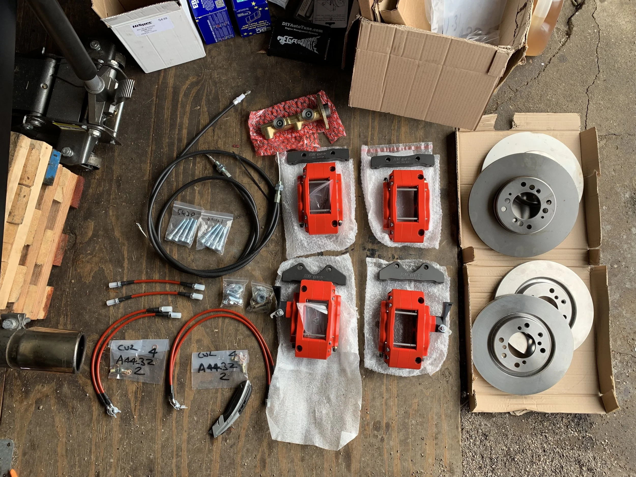
My new Big Brake system
Front brakes
I started the installation with the front brakes. The new disc bolts directly to the back of the original hub with the four original bolts and a 13mm wrench. The hub then slides back onto the axle, and the rear nut and front nuts are re-installed to secure the hub and rotor assembly.
The caliper sits on a new mount that bolts to the back of the hub. Be sure to use the spacers included with the mount and caliper — don’t and confuse the spacers and the washers. They are clearly marked, and are slightly different thicknesses. If you install the wrong ones, the caliper won’t sit centered on the rotor. If you see that it’s not centered, you swapped the spacers and the washers and need to do it again with the correct spacers. This is outlined in the instructions that came with the kit.
I installed the brake pads next. This is good to do early as it makes it easier to tell if the rotor is mostly centered on the caliper, and thus if you correctly used spacers instead of washers during mounting. The pads simply slide into the caliper, then the pins are slid through the holes in the sides, and a cotter pin is put through the hole in the pin. Note that the cotter pin goes on the outside of the pad, not the inside; the latter would keep the pad from being able to move towards the rotor. The last step is to install the anti-rattle spring under the pins.
Next install the medium length brake line from the kit between the caliper and the had line. Be sure not to over tighten the lines to avoid damaging them. Reuse the spring-like protector that runs along the line to keep it from being damaged by the metal parts of the car.
Using a 13mm wrench to attach the new rotor to the front hub.
Sliding the first brake pad into the rotor.
The first pin installed, with its cotter pin inserted on the outside of the pad.
The second pin partially installed. The anti-rattle spring is already attached for clarity, but normally it would be installed after the pin is fully inserted.
The new brake line installed on the hard line. The spring-like protector was installed over the line later.
Final installation of the front rotor on the driver’s side.
Final installation of the passenger side rotor. The brake line can be seen on the right side of the image.
Rear Brakes
The rears are a bit different. Due to how the rear brakes are held, you won’t actually mount the caliper onto the rotor yet.
There’s a mount that needs to be installed using the original mounting holes; I did this first. I then attached the short brake line to the caliper. The long line is connected to the hardline on in the car, and then to the short line that goes to the caliper. This replace the old hard line and makes it easier to remove the caliper for bleeding.
This is as far as you’ll want to go before you’ve bled the system (but after installing the pads), but I’ll cover the final installation here: slide the rotor onto the axle, then slid on the caliper and secure it to the mount. The caliper’s bleed screw points down in the DeLorean configuration, and the handbrake bracket points up. To ensure the rotor is correctly seated, you can either temporarily fit the wheel or you can get some large washers to simulate the wheel thickness and tighten the lug nuts onto those. I did the latter, since I could see the caliper more easily. It also made it easier to tell if I’d used the correct washers and spacers in the right place by making sure the caliper was centered on the wheel.
Next insert the brake pads as per the front wheels, and you’re all set.
I did have a curious experience where I could easily rotate the front wheels by hand, but I could not rotate the rear wheels with the new calipers installed. As best I can tell, this was due to the brake pads being a bit tight, but they would break in over time (the GreenStuff pads have a sacrificial burn-in layer on them). I should also mention that the engine was able to turn the wheels trivially, simply by having the transmission in Drive without pushing on the gas at all. A little scraping from the new pads is normal, too, and goes away after a few miles of braking.
The mount bolted onto the hub carrier behind the new rotor.
The mount for the caliper installed to the hub carrier.
The 9/16 socket needed to remove and install the brake caliper mount.
The caliper being test fit. Note that the brake lines are installed incorrectly here — the short line is attached to the hard line, and the long line is attached to the caliper.
The new short brake line at the trailing arm.
The correctly installed rear brake lines.
What happens if you accidentally swap the washers and spacers. Notice how one of the pads (green) is pushing against the rotor (silver) (left) while there’s a gap on the other pad (right).
The caliper correctly centered on the rotor.
Hand Brake
The hand brake is a bit of a pain. I had to remove the driver’s seat to get the cover off. This is done by removing the four nuts on the studs going through the floor of the car from underneath the car, and simply lifting the seat out.
The hand brake cover is held in place with a couple of plastic snaps, which can be popped out from the side. You can then lift it up and forwards. It may be necessary to remove the rubber on the hand brake lever, which just slides off while twisting.
The cables simply look onto the lever. It is recommended that you zip tie the ends of the cables together so that they don’t fall out. They are a bit of a pain to get to since you only have a small access in the side to fish the cables through. Once unhooked, the cables should simply pull out the back of the hand brake assembly and then through the car body from the outside. Be sure to keep the grommets that the cables run through, as you’ll use them on with the new cables.
The new cables just run through where the old cables did, reusing the existing grommets, and connect to the lever in the same way.
On the caliper side, the brakes slide into the hole on for the hand brake bracket, then hooks onto the lever itself. To actually hook the cable onto the lever, you’ll likely have to remove the 10mm nut on the lever, hook it, and then tighten the nut again.
The two nuts lock against each other on the outside of the bracket, and are used to adjust where the cable sits to avoid pulling on the lever while also not slipping off of it. In my case, there was always tension the lever for some reason, so I had to remove the notes entirely. The hand brake still works fine, though. I’m not sure why I don’t need the nuts.
The original hand brake cables connected to the brake lever.
I also removed the brake lever, but this doesn’t actually help, other than giving a better understanding of how the mechanism works. The ends of the cables can be seen here as well. They slip into slotted holes the silver bracket at the base of the lever.
The new cables installed on the hand brake lever. The black zip tie helps sneers the the cables don’t slip off on their own.
The cable hooked onto the hand brake lever on the caliper, with the two nuts sitting outside of the bracket. The nuts should be adjusted so that there is no tension on the lever when the brake is not in use.
I seemed to always have tension on the hand brake lever when I used the nuts, and finally just removed them. The brake still works fine like this in my car.
Filling and Bleeding the System
Filling is done just by pouring new fluid into the brake reservoir. Always use new fluid, and always used DOT 4 fluid. DOT 4 operates at higher temperatures than DOT 3. Do not use DOT 5, which is a synthetic fluid that does not absorb water. The DeLorean brake system is not completely sealed, and water will get in. DOT 4 is designed for this, but DOT 5 is not and will cause problems over time. You also need to change your brake fluid every two years because of this property, as the fluid becomes saturated with water.
Bleeding is done as per the instructions provided with the kit. The DeLorean effectively has two separates systems, and the lines are equal long, so it doesn’t matter which caliper you bleed first, but convention is to start from the one most distant from the master and end at the one nearest. In the DeLorena, that’s rear right, rear left, front right and front left.
To make bleeding easier, I used a Power Brake Bleeder from Motive Productions. This is a plastic canister that you put brake fluid in, attach to the reservoir cap, and then pump up to build up pressure. This simulates pumping the brake pedal to push the fluid through the system and avoids the need to have two people to bleed. Be sure that you don’t run out of brake fluid while doing this, or else you’ll introduce air into the system and have tc do it all over again.
To bleed the rear calipers, you need to unmount them from the hub carrier mount and position them so that they’re vertical. This is how the fronts are mounted, and how most cars have them mounted, but the DeLorean rear mounting position requires that they be removed to be bled.
To avoid trapping your fingers in the rear calipers, place a block of wood where the rotor would be inside the caliper for safety.
You can now bleed the system, always bleeding the one closest to the master cylinder first. Remember that these calipers have two bleed screws, so start with the outermost screw, then the innermost one. I did a circuit around the car, then a second circuit, then left everything overnight as per the instructions. The next day I did one more bleed before assembling everything.
You should now be all done — check the brake level and make sure it’s at the MAX marking (I had to remove a little fluid myself). Then just replace the master cylinder access cover, re-mount the calipers and wheels, lower the car, and go for a drive.